So the first question ,you would ask is “why ?” the answers are pretty compelling but i would put the reasons as
you just want to upload your VM estate straight into S3 ,and then use the fat pipe between EC2 and S3 (40 – 50 megabits per second) to use S3 to boot EC2 .
you want to have a bootable AMI instance but AWS does not seem to allow this,so its a bit like in VM using a bootable ISO to build your VM , AWS does not allow you to mount ISO and then reboot their AMI’s from disc.
We going to use PowerShell to move users – but there’s quite a bit to consider when migrating, key to which is understanding the driver of the cloud adoption
pro list cloud adoption
Cost – companies can make a considerable savings in TCO , this is a big driver , migration paths are often designed to end when the next big contract is due to be signed for the vendor – though sometime especially when you analyse the costs it can be that the client is paying more – cloud is not cheap and you have to be wary of how things are billed
New functionality – the pandemic has only served to poor gasoline on the fire that was pre-pandemic cloud adoption ,the web stack is literally the coal face WebRTC and just the way teams does that job of searching and allowing the user to become his own web 2.0 knowledge base by searching through meetings and screen shares and documents all through the same interface means that the way your data is stored is more organic and of course not tied into your laptop, companies with a high emo intel understand that teams helps its users by allowing them to find their own answers which is only empowered by the way teams collaborates with the users
Cons list Cloud adoption
Teams URI need to have a unique e164 number pattern – this means that every number on teams is uniquely dialable , that might not sound like a limitation but back in the day of Enterprise PBX deployment you could have an internal number that wasn’t part of the dial plan but that presented an external phone number mask that was contained within the dial plan to the trunk which would be accepted by the provider- so to put this right ? you must upgrade your DDI lines to remove these internal partitions -though these can be difficult to detect
There are plenty of enterprise functionality which may not map in the cloud such as functionality in the analogue space, forwarding calls direct from the AA
because of the URI requirement this means that PBX 4 digit dialing or any custom schemes that the user were used to – will no longer work
in the MS world a line URI must have an AD account for it to work, so lines that don’t have associated users or AD accounts can’t be migrated
Pre migration check list
Interworking from the cloud perspective is realised by number plans and proxy sets, which select where you want the call to go
Interworking from the IP PBX perspective it is realised by number plans that use SIP trunking to the SBC and MS integration
Hybrid platforms mean that the act of migration becomes moving the line from enterprise to cloud and then cleaning the PBX
A PBX DDI and a Cloud telephony URI can’t exist in the same systems, so if you got a DDI line of 1111 and a Line URI of 1111 the architecture can’t route the call
The pre migration test list
Check the site hybrid functionality – make inbound and outbound calls via cisco and make inbound and outbound calls via teams, test call forwards in both systems any analogue dependencies and IVR functionality don’t make any assumptions it will help to understand the dial plan
check the PRI count how are the numbers delivered into the architecture
Dump the IP PBX dial plan into excel – capture MAC addresses if you need to reverse any lines out of the migration – don’t delete what you don’t want to hide it
Dump the corporate or replicated AD into Azure AD and get it into a form that doesn’t kill any LDAP replication and put it as a tab in the worksheet
Hide elements you can’t migrate because of the functionality for teams the main ones tend to be phones in kitchens because chef doesn’t own a computer etc
make sure that we a number is not internal for example, check to see if the extension fits the dial plan – test ones you think are internal
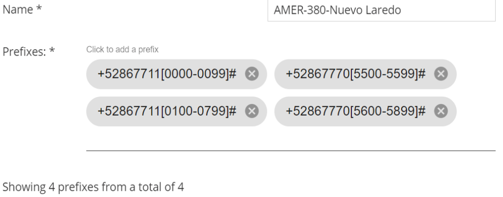
check that the prefix groups in Audiocodes routing manager match the PBX ranges to migrate, this can also help detect internal extensions
track shared lines in the PBX
build your teams spreadsheet incrementally by hand which you will use to PowerShell to the cloud
Direct Media and Local media Optimisation
Direct media is where an e1 is terminated in an SBC that the enterprise manages. LMO is streaming media direct to an internal interface of an SBC, so you don’t have to stream over the internet. the following deployment topologies build the signaling and, media paths so you can build to understanding LMO
This should be in its own blog but i am going to attach it here, its key to understand the flows
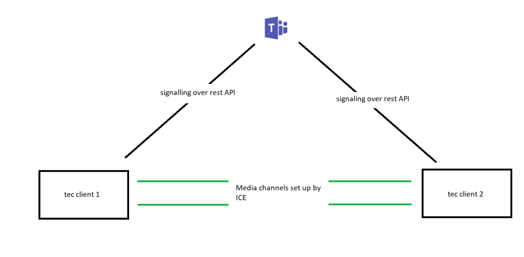
Teams’ client talks to team’s client signalling
In this scenario the REST protocol signals the teams Microsoft cloud
teams to teams
teams to team’s client media
Its down to ICE to handle the media fixup
media is handled by ICE
It’s the firewall and ICE’s job is to get the media in the best way possible between clients and it may use functions within the Office 365 network such as transport relays (media processors) if there is no direct path
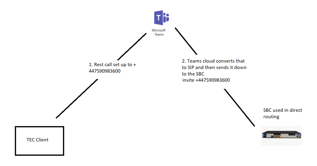
Teams’ client to SBC signalling
endpoint generates the rest request and teams converts to an SIP invite and sends to the SBC
teams SBC signalling
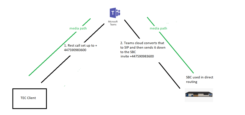
TEC to SBC media path without bypass
media path to teams’ cloud
typically, the media can go through teams, but that isn’t the optimal path which would be between the client and the SBC
Media bypass
it’s quicker to go directly from the client to the SBC or centre media directly from the card to the SBC so in this case what we can do is enable something called media bypass now we’d pass bypass came out about a year ago it was just to basically a tick box in the configuration of the SBC you just said turn on media bypass and then teams will try to set up the call so the media will go directly from the client and straight across to the SBC
Media uses Silk codec ICE carried this media as well (Opus has been deprecated)
Client external to the SBC without media bypass
Without media bypass the signalling and media go from team’s client ot the SBC just like the TEC to SBC path
external client without media bypass
Client external to SBC with media bypass
with media bypass
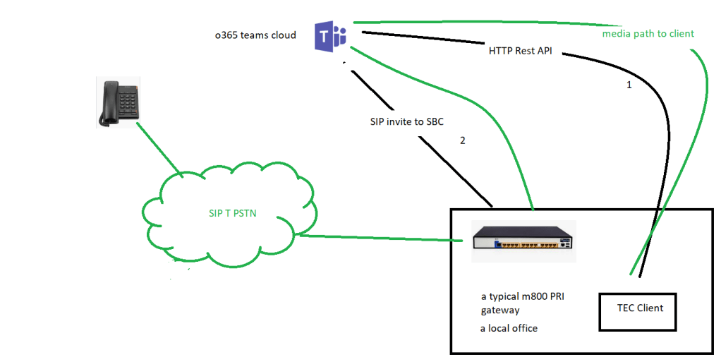
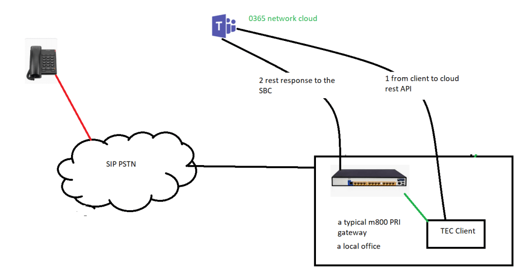
client local to SBC without media bypass (m800 with PRI )
hair pining through 365 clients
this stresses the firewall since we can see we are proxying through the client, also if the client is on the same LAN segment as the gateway the traffic is not optimal
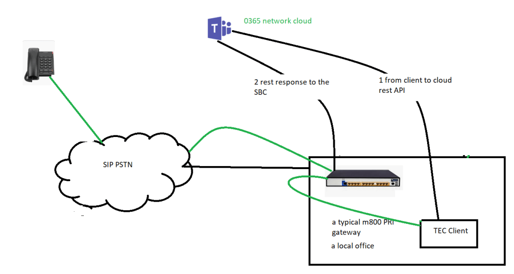
Client local to SBC with media bypass (m800 with PRI)
how you would hope the media to travel
you would hope that with media bypass the client would stream media direct to the SBC
but one of the limitations of ICE lite was that the SBC could only have one IP address which in this case is external facing toward the PRI interface
this meant that the media had to exit and re-enter the firewall
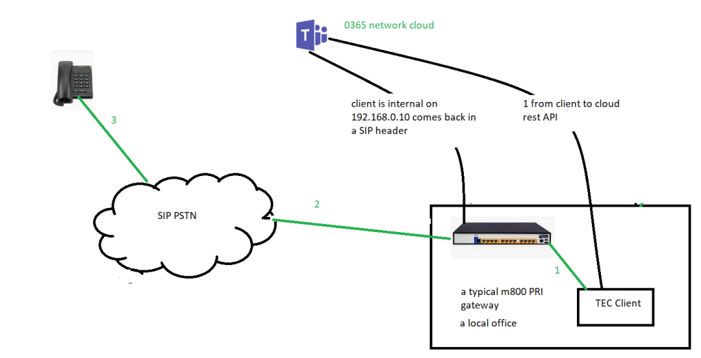
Local media optimisation solves this
it’s an enhanced media bypass, it uses Lis and LBR data to have location information
new sip headers include information about the user location
“external” or “internal ” in terms of the corporate network
this gives us smart call handling with more flexible topologies
you can still set up media bypass without LMO
prerequisite for LMO
configure sites and networks in teams using PowerShell new-CsTenantNetworkSubnet to define network subnets and assign them to network sites. Each internal subnet may only be associated with one site. Tenant network subnet is used for Location Based Routing.
for example New-CsTenantNetworkSubnet -subnetID 192.168.0.1 -mask bits 24 -siteid london once its set up it can give you significant advantages
Local client use ‘internal’ header for media
client is sitting on the same LAN as the SBC
with LMO
so, with the flag internal or external, site information and trusted Ip address, this means that the sbc can work with the client
the media flows through the SBC on an internal sip interface to the external SIP interface and out to the cloud
we are not constrained by ICE Lite which means we only have 1 ip for media, and we do not hairpin the firewall
client is external to the SBC with LMO
looks like nothing has changed
but codecs come to play here, the implication being that the SBC has got to transcode between G711 and SILK
transcoding is a heavy lift
but if you were an internal user you don’t have to transcode because the SBC will assign you to the G711 group and doesn’t have to transcode
Cisco hybrid site testing
find an IPC session and get it registered look in the PBX for test description and check inbound and outbound routing for the IPPBX side of the house and teams
check on the way the PRI or the SIP trunk is delivering calls into the site
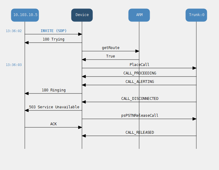
so this site looks like a typical M800 / E1 gateway deployment with local media optimisation
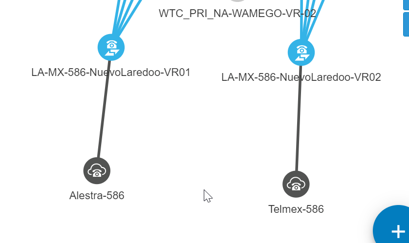
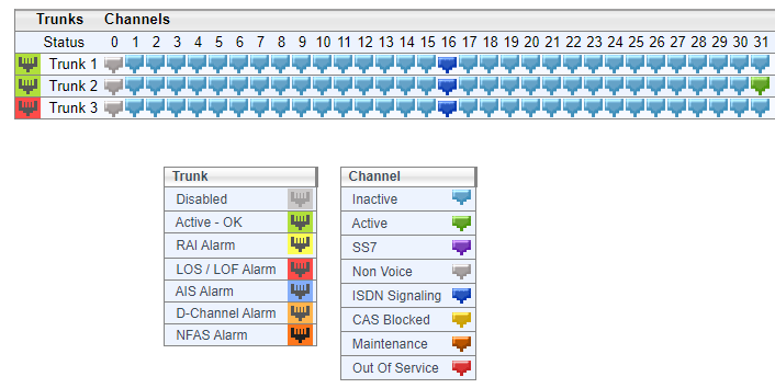
2 PRI architecture
4 connections in this implementation of teams, to the regional SBC (x2) to the MS voice proxy for teams (x2)
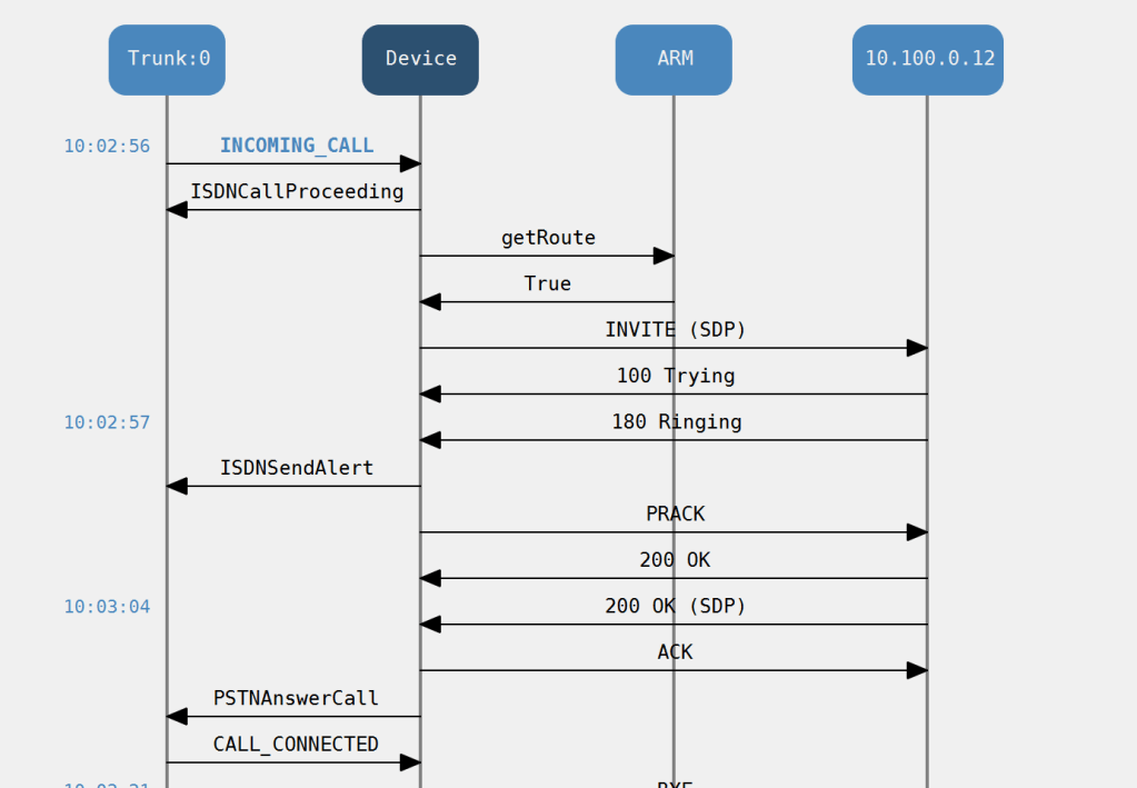
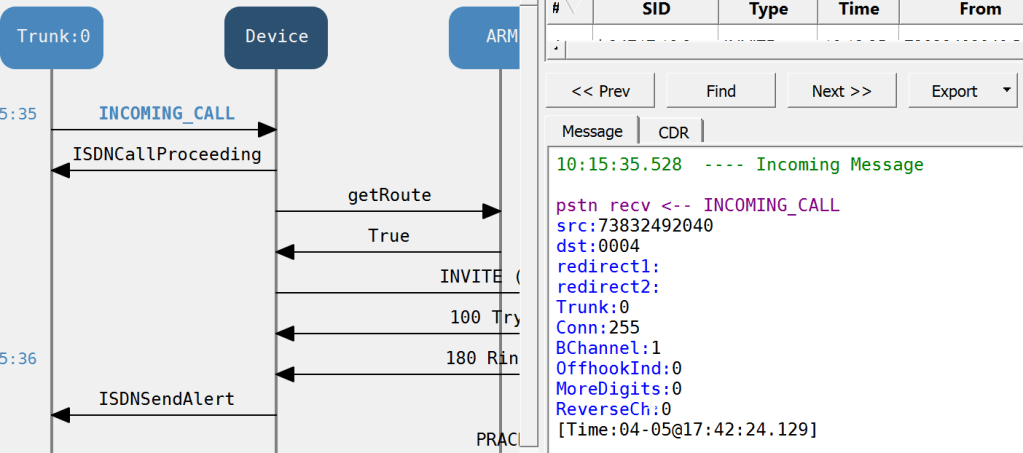
Inbound PRI call Cisco in Nuevo Laredo
Let make a check that the PRI is delivered by syslog to the M800 GW on VR01
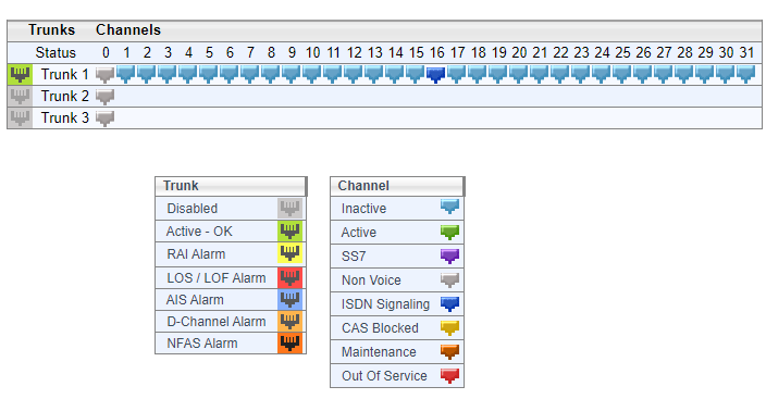
So, if you done it right you will see the trunk
to save my mobile cost i took advantage of the following feature SIP that is you can use a diversion header for a unregistered device
PRI Voice testing in VOIP environments trick
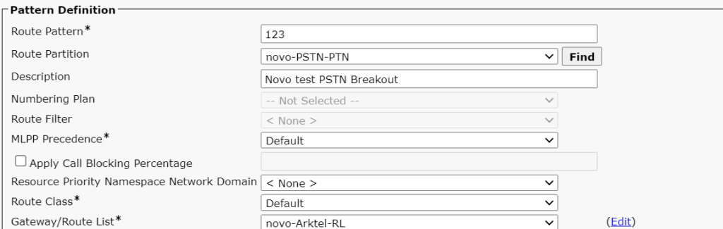
Pick a legacy site with a E1 termination and create a custom route pattern to carry your number for example
my 123 pattern to making calls from russia
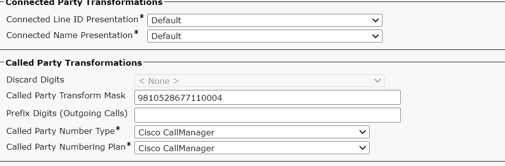
then use a called party transformation for the number you want to target via the e1 call
to my E1 in the site
then you can choose any extension in the partition or associated CSS
this could be any unregistered endpoint
but against the line
took a gamble on the Forward CSS but mobile is good for most
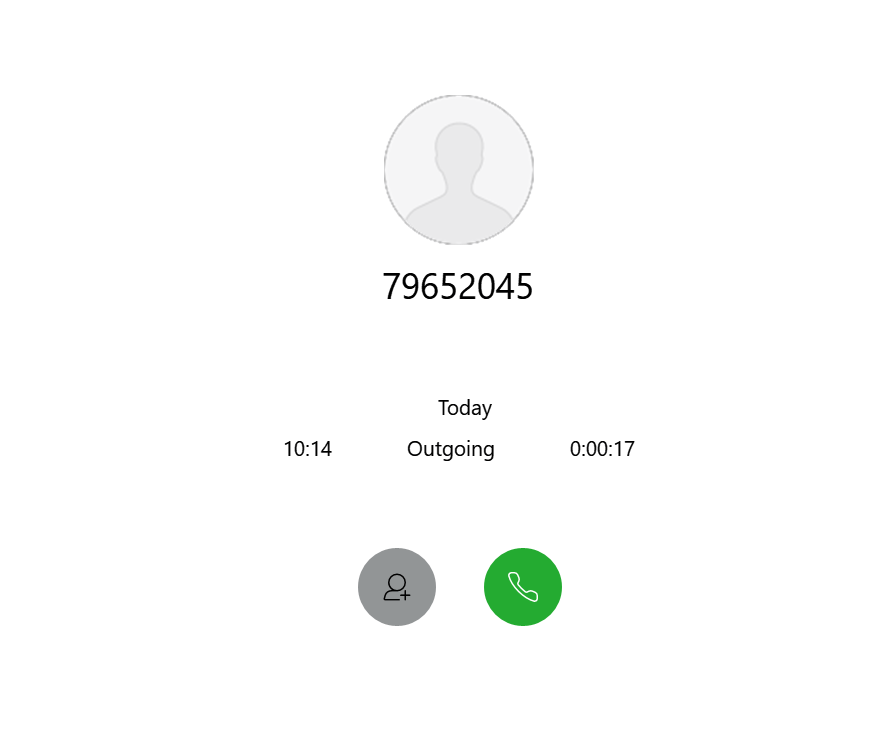
then all you have to do is exploit the VOIP dial plan by dialing the forwarded extension over VOIP dial plan
and then you would generate the trace above
Site PRI testing results
investigating the inbound call
inbound PRI call
This PRI is sending 4 digits – can it send 9999 if you bust the dial plan you get to hear the local provider, but does it hit the gateway first? i don’t think so since if you scan the syslog for a CUCM event there is nothing
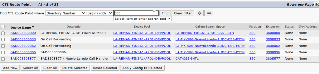
some interesting things to test would be the main number for the CTI which is on which in this case we can use to test dtmf as well
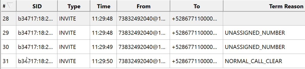
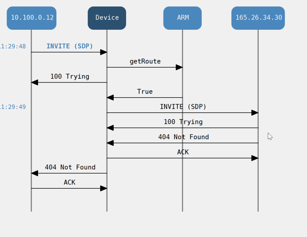
it made 4 attempts to route the call
These extra events where to the Microsoft voice proxy HRD
why MS proxy
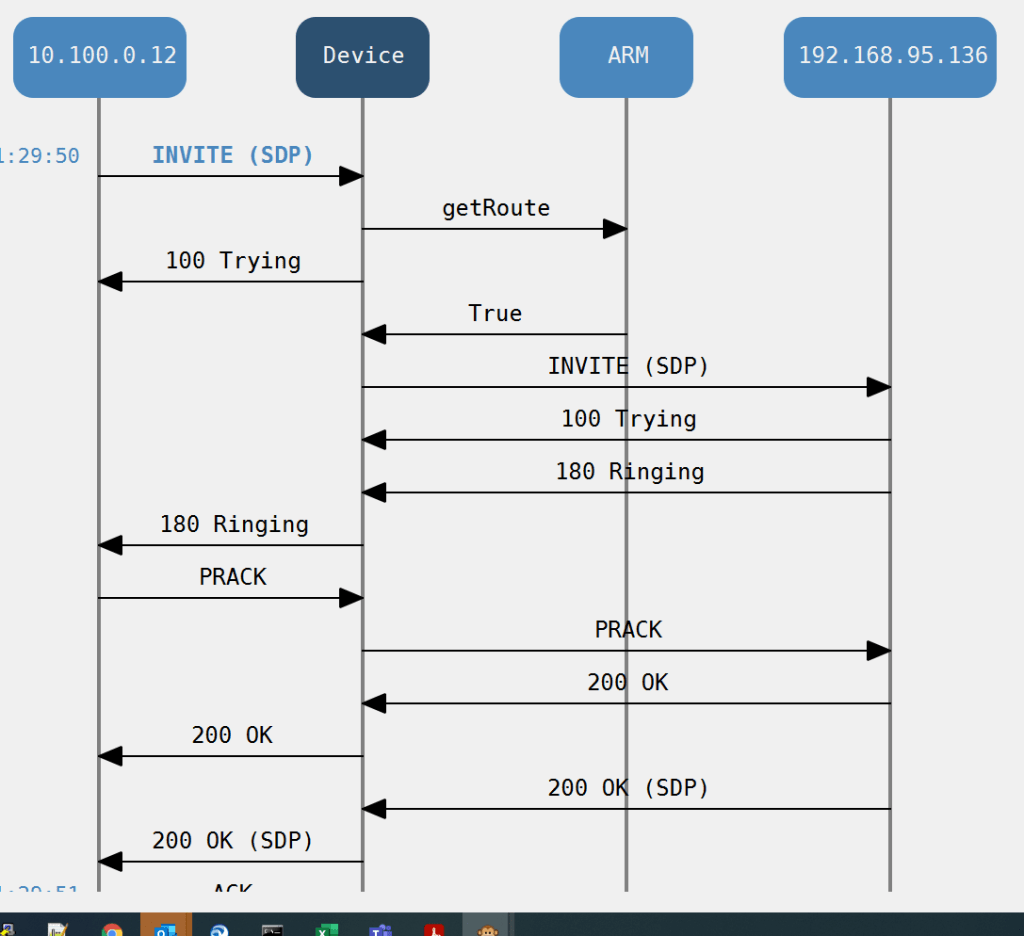
but then finally we end up on the Voicemail Unity call handler
unity call handler
so here’s another thing a forwarded line to the call centre
these are gateway dependent since 5599 is the other provider so you won’t see it on the first PRI
there was quite a lot of delay so i wonder if it’s hunting out the HRD again only 1 way to find out
Cisco Hybrid points
The CLI is different for when you present the outbound call to the SBC vs a VOIP call to the enterprise
The call tries the HRD SBC before routing to the local gateway for an inbound call
if you blow the prefix group or trunk DDI the operator cuts in
we can immediately start to build a map of numbers that we can’t migrate because of forwards
Cisco Enterprise AD teams Migration data
The act of migration from enterprise to cloud is an exercise in data manipulation, IP-PBX feature migration, power shell pipeline , Teams administration , IP PBX cleanup and then teams site verification
The three things you need to migrate a site
The DDI lines to be migrated so they can be written as a line URI
The data has to be Azure AD ready, specifically MS needs an email address for the domain of the DDI user which is used as a UPN
A voice Policy
There are others but they are more about setting up tenants and cloud instances
Definitions
A User Principal Name (UPN) is an attribute that is an internet communication standard for user accounts. A UPN consists of a UPN prefix (the user account name) and a UPN suffix (a DNS domain name). The prefix joins the suffix using the “@” symbol. For example, [email protected]. A UPN must be unique among all security principal objects within a directory forest.
The line Uniform Resource Identifier (URI) must be specified using the E. 164 format and use the “TEL:” prefix.
A voice routing policy is a container for PSTN usage records. You create and manage voice routing policies by going to Voice > Voice routing policies in the Microsoft Teams admin center or by using Windows PowerShell. … Users will automatically get the global policy unless you create and assign a custom policy
Prefix Groups make routing management and Dial Plan management easier, more efficient, and more convenient for telephony network operators. The feature also makes it possible to import an existing customer’s Dial Plan into the ARM using the northbound REST API.
Every routing rule can have dozens of prefixes. Grouping prefixes and then associating groups with routing rules reduces visual complexity and allows for more effective management. Prefix Groups save operators from repeatedly having to add prefixes to rules.
Once defined, the Prefix Group comprising multiple prefixes is associated with a routing rule
for example, an enterprise has distributed offices, the following can be defined: If a caller calls from source prefix x, the call is sent from SBC 1; if a caller calls from source prefix 2, the call is sent from SBC 2.
To develop a customer-specific Dial Plan into an ARM Prefix Group, the REST API is available.
PBX dump
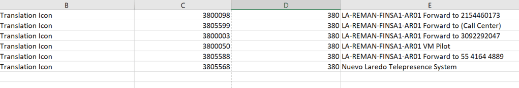
If the PBX has a web interface select copy and highlight and paste special into excel as plain text, you will end up with the below
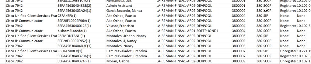
CUCM IP Phone by Directory number
it also is worth understanding the translations that get us here from the PBX where the voice trunk number is normalised to the PBX dial plan
oh look some forwarded lines
it’s also worth knowing how unity connection connects into the site
ooh look some forwarded lines
it’s worth putting this routing in the excel spreadsheet as different tabs
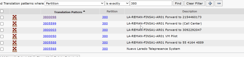
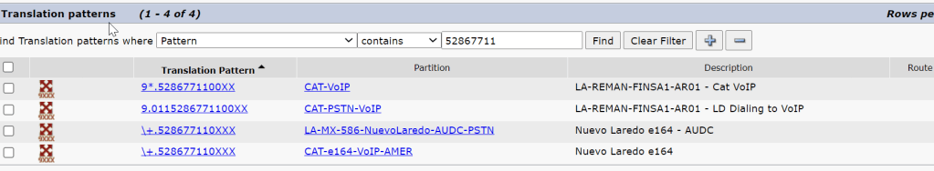
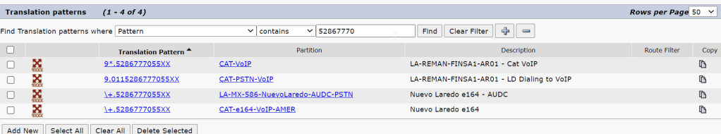
there must have been a translation pattern from when the e1 migrated so there must be a translation for a prefix group
ARM routing prefix
and look if we do that
PBX translations
change the query to check the other range
i translation per range
Please automate me Building the list
This is where we need to manipulate that data
Frustratingly there is no import excel type module like here by default and i dont want to risk my pipeline since i only have just got my MS to connect so i guess i need to build more into my excel or strip out the data to a file system
if you do all the descovery you will end up with something like this
Migration data set
PBX dump
name phrase /DDI
string
PBX dedupe
DDI
string
CTI
DDI
Translation profile
DDI range
string
Mask / Range
DDI by mask
string
Power BI
UPN ,UID
String
Clues / AD
DDI
String
Prefix
DDI range
string
so to create an engine to work out the eligibility purely on the basis of a string search task -hmm
Putting the pre migration check list to the test in Sao Palo
lets fine tune this list and put it to the test , i have to finish of the migration of a site in Sao Palo – it did have two physical sites fronted by a cisco voice gateway with a PRI interface , but they then split the site in the cloud / teams and deployed an m800 gateway
checking the ARM network map Architecture
network map for Sao Palo
The site has mulitple voice connections
The site has multiple voice connections , jsut like where i had joberg with one SIP trunk and one PRI split accross the gateways
la-br-1673-saopaulo-audc-vr01
VIP VOIP PRI 1_la-br-1673-saopaulo-audc-vr01_VoIPPeer
VIP VOIP PRI 2_la-br-1673-saopaulo-audc-vr01_VoIPPeer
from the prefix group it looks like 3 ranges has been configured where some how we get to extension 2300 on a new addon to the range
+55112109[0700-0799]# for RNX 425 site 1673
+55112109[2000-2099]# for RNX 424 site 373
The financial prefix group looks like the best place to be since it covers all the ranges
Sao Palo Site 2 analysis
They have split the site logically but it share a continous range , but lumping 373 into 1673 might be a bit of a management head ache , but is possible , as log as thier is no duplicated extensions in the
so i am curious when it was on a cisco controlled PRI how did the cucm manage that ?
CUCM translation pattern config
translation patterns containing the range
site 373 ranges
site 2 373 ranges
site 1673 ranges
site 1 1673 ranges 2nd range
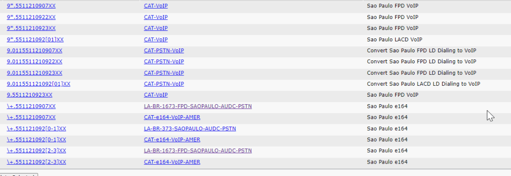
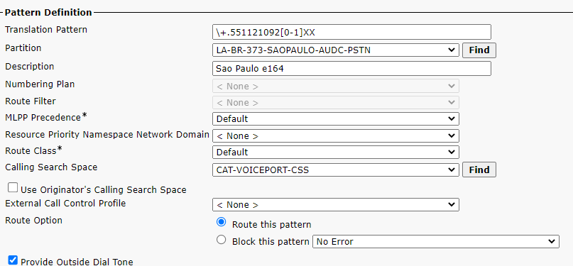
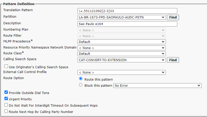
sanity check the ranges
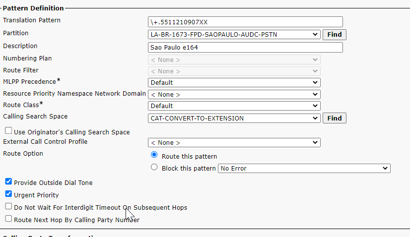
\+.551121092[2-3]XX any extension starting 22 or 23 belongs to site 1
\+.551121092[0-1]XX any extension starting 20 or 21 belongs to site 2
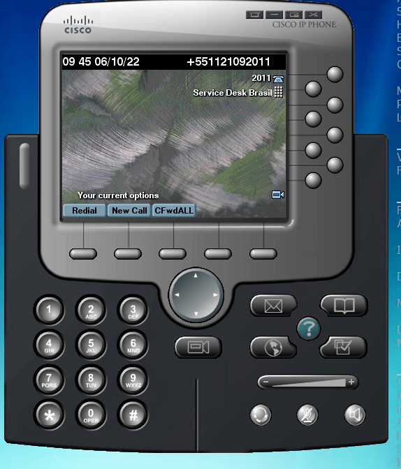
Site 2 id 373 test device Cisco
test device site 2
so lets sanity check the 1st pre migration check list which was to test for hybrid working
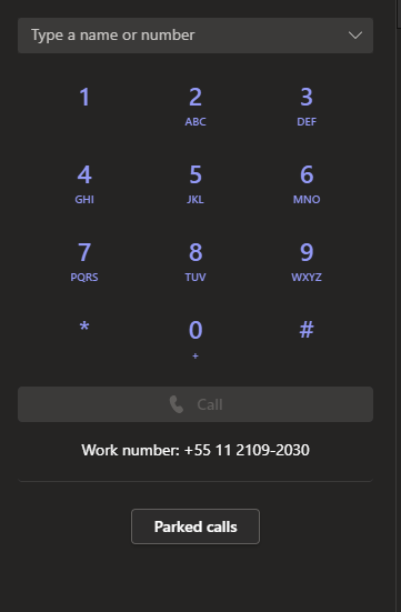
site 2 id 373 test device TEC
TEC test device
Check the site hybrid functionality – make inbound and outbound calls via cisco and make inbound and outbound calls via teams , test call forwards in both systems any analogue dependencies and IVR functionality dont make any assumptions it will help to understand the dial plan
A genius
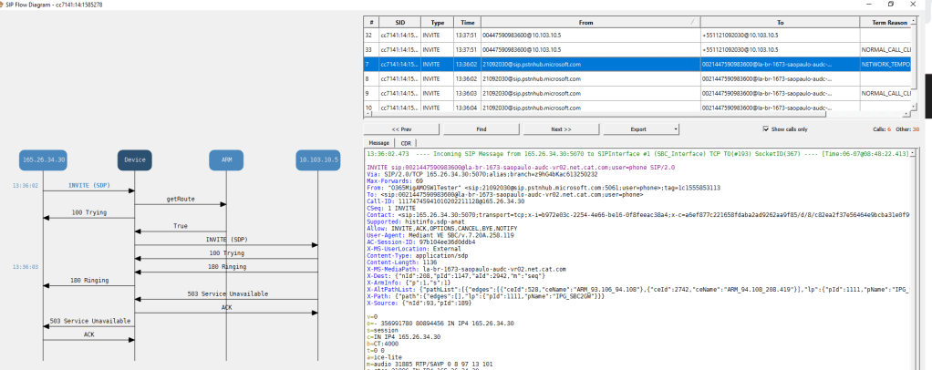
inbound call testing site id 373
inbound call came in on 10.103.10.5
in bound calls got this number cant be recognised
Site 2 id 373 test endpoint TEC
Neither inbound or outbound worked mainly because the normalisations seemed incorrect outbound calls where being prefixed by 0021 and was dropping the + (if you look in the invite below)
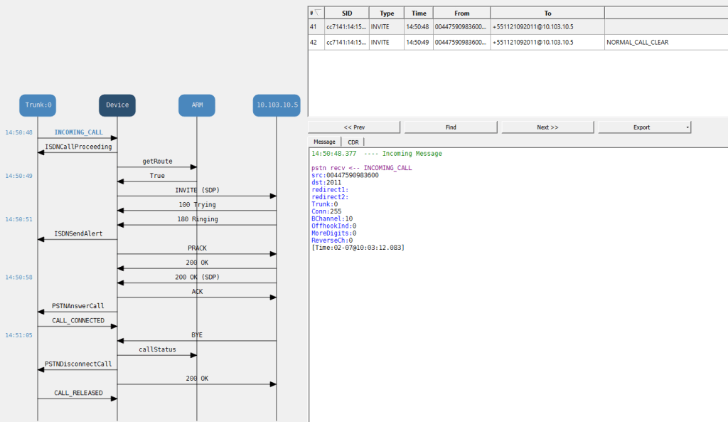
Inbound TEC call
inbound calls got number not in service
Outbound call testing TEC
this worked ok dialing the full e164 pattern within Brazil
Things get interesting
So the site migration check list through up some interesting , that when we put a line in that second range we are hitting an outbound destination manipulation profile that doesnt support e164
outbound dialling from cisco prefixed a +55 which is an easier fix
let break down the teams inbound call
whats puzzling about this is that the site 1 / 1673 / 425 which works perfectly for TEC (id/rnx)
site 2 /373 /422 doesnt and we hit the number not in service annoucement for Cat
The inbound call gets this number in not in service for caterpillar , and this sugests that the pattern may be in CUCM , we see the voice mail kick in on the sdp which i guess is the steve bergstrom voice , but cucms kicking in to say that the number doesnt exist
the outbound call is picking up this prefix 0021 instead of a plus when it tries +44
this is what the invite looks like
invite for the outbound
spot of ARM testing
turns out there is the following manipulations
so which site is which
turns out we could update the table as to whether a site is CBLC or financial
so wheres my prefix come from
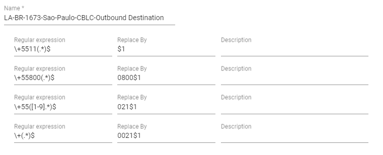
Outbound destination prefix
so anything that starts with a plus gets prefixed with the 021
when i tested with my mobile
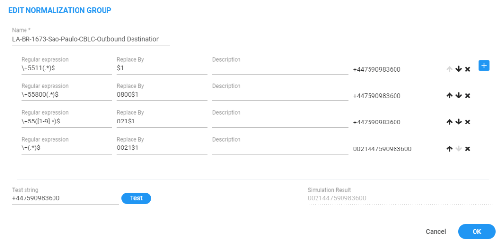
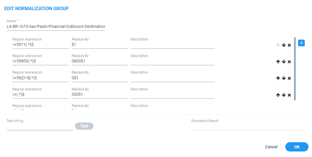
ARM normalisation
so it should hit the first pattern but its taking the 4th as you can see in the first SIP header
First SIP Invite comes in with 0021
so can i get the 021 from the other normlisation
short answer no
so this normalsation doesnt append but when we test it
top bins
The final part of the mystery
there must be a link between the prefix group and the manipulation – which purely depends what digits you put out there
the tale of two routing rules
financial CBLC
LA-BR-1673-Sao-Paulo-Financial
SOURCE
Prefix Groups:
Ⓖ LA-BR-1673-Sao-Paulo-Financial
DESTINATION
ADVANCED
Notify when activated:
false
Prioritize call:
false
Registered users:
false
Request type:
Call
Privacy policy:
Transparent
CALL TRIGGER
Initial:
true
Refer:
true
3xx:
true
Broken connection:
true
Fax rerouting:
trueACTIONS
ROUTING
Method:
Sequence
ACTION
Priority: 1
VIP VOIP PRI 2 (la-br-1673-saopaulo-audc-vr01) , Src Man.: LA-BR-1673-Sao-Paulo-Financial-Outbound Source ( From, PAI, PPI ) Dst Man.: LA-BR-1673-Sao-Paulo-Financial-Outbound Destination
Priority: 2
VIP VOIP PRI 1 (la-br-1673-saopaulo-audc-vr01) , Src Man.: LA-BR-1673-Sao-Paulo-Financial-Outbound Source ( From, PAI, PPI ) Dst Man.: LA-BR-1673-Sao-Paulo-Financial-Outbound Destination
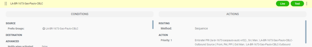
drag_indicatorLA-BR-1673-Sao-Paulo-CBLC
LA-BR-1673-Sao-Paulo-CBLC
CONDITIONS
SOURCE
Prefix Groups:
Ⓖ LA-BR-1673-Sao-Paulo-CBLC
DESTINATION
ADVANCED
Notify when activated:
false
Prioritize call:
false
Registered users:
false
Request type:
Call
Privacy policy:
Transparent
CALL TRIGGER
Initial:
true
Refer:
true
3xx:
true
Broken connection:
true
Fax rerouting:
trueACTIONS
ROUTING
Method:
Sequence
ACTION
Priority: 1
Embratel PRI (la-br-1673-saopaulo-audc-vr02) , Src Man.: LA-BR-1673-Sao-Paulo-CBLC-Outbound Source ( From, PAI, PPI ) Dst Man.: LA-BR-1673-Sao-Paulo-CBLC-Outbound Destination
calling restrictions enforced by outbound destination CLBC
what i am hitting is the CLBC translations which for that circuit uses 021 as the trunk access code to dial the e164 pattern
if you dial a number in brazil as the +55 it works but it wouldnt be good to offer , but it was nice to get a connected call
it basically looks like that this call center is not enabled for TEC e164 dialling so we just got to make that work in the outbound and inbound manipulations for CLBC to see how close we can get
Conclusion maybe a week later……..
The list that the lcon gave had users from rnx 424 site 1673 which had already been migrated so that really put the cat amongst the pigeons , but the extension range for these already migrtated users was right for 1673. Inbound and outbound teams calling worked for the site and restrictions where enforced the only thing that didnt work was international outbound but the outbound manipulations where built to just enforce brasil outbounf no where else
when i was younger and living with my older sister – she put a physical phone lock onto the phone dial so it couldnt be used , such as the one below
This meant that the phone was unusable to make calls – you could receive calls fine . Since i was quite smitten with a girl that i wanted to call i observed that when the lock was off and i could make a call, when you dialed a 3 you would hear like 3 connections as the analogue swicthing units connected for a 3
This was exactly the same sound as you would hear when you lifted the reciever and the circuit to the telco was esatblished , if you lifted the reciver and pushed down the swicth that let the phone know you was off hook you can hear the dialling – so if you wanted to dial a sequence of numbers you could just tap them out on the phone and then you would get connected
later on in my career when i worked for a telco the analog guys used to have these swicthing units on thier desks ( like the ones below)
they where platinum tipped and so quite valuble, it was the noise of these connecting that i heard all those years ago ,when you depressed the off hook button on the phone the voltage changes went across the local loop to the exchange , where the stowgers would register the voltage change as a signalling attempt
fast forward to my latest issue – i have an audiocodes M800 gateway with a SIP trunk connection to a carrier , if i dial through the trunk to the M800 and then forward the extension to the CC where we have to enter some DTMF – the CC could not hear the tones
teams with optimisation do not play nice with e164 addressing – that is to say for the teams direct optimisation to work we need a e164 adress for hosts that in the site subnet
i am a bit pressed for time – but this is the problem when you deploy the e1 you may size it for growth and get it wrong- resulting in maybe some PBX based routing and some internal extensions which dont immediatly translate into a true e164 address
but how do you find them and know you got them the first way would be a simple extension count if you got more endpoints than DDIs in your e1 circuit then a PBX designer has got clever with the dial plan
The phone number mask trick
This allows you to make a call from an internal number by using a mask that is in the public DDI range. This means the E1 circuit will accept it but you cannot ring it back but you could use an IVR to redirect to the internal range for inbound
Stick it in the Public DDI
best way to tackle this is with some SQL
run sql select dnorpattern, d.description, e164mask, tkpatternusage from devicenumplanmap inner join numplan on fknumplan=numplan.pkid join device d on fkdevice = d.pkid where e164mask= “+52867711XXXX”
choose your mask against Publice DDI ranges if you got extensions in this range that dont trannslate
The SBC outbound source trick
This just makes the manipulation for the public range at the SBC
Normalising Internal to External
its doing the same thing we are normalising to a public number – this would be good for contact centre routing instead of making them non dialable by some other means
Testing Direct Media optimisation
For direct media optimisation to work we need ;
subnet , to punch the media to from the internal sip interface to the site E1
It aslo must see VPN addresses as a site address
Calls from the public internet are external calls
The WebRTC element must work for both
The media must be encypted
Call forwarding and other re directions must be supported
we got to able to transfer
we got to eb able to hold snd retrieve
Internal IP streams flow via Internal SBC sip interfaces
External IP streams flow via external SBC SIP interfaces
so in its way this defines a test list
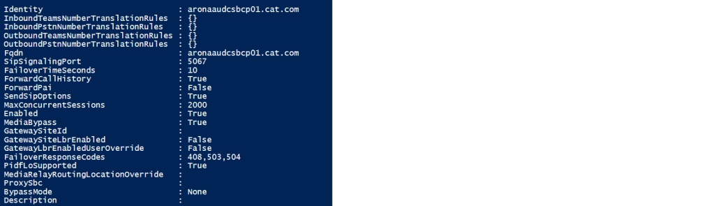
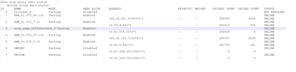
Dump SBCs in the environment
Get-CsOnlinePSTNGateway is going to dump all the PSTN gateways – which are configured to allow the internet reach voice networks – they are a list of SBC SIP interfaces
There are a few global truths – if we have an M800 with with an E1 – than that is the resource we want to control at a site based SBC – i mean we could by means of manipulating call number masks and ARM ( brain ) maybe exit via one SBC and enter by another – this is acceptable in the SBC verse and i will test this later but here we want to control what the site based E1 can do via the SBC – so before we brought a SIP interface into the SBC – this would of meant we manipulate in the Brain – and its slave army of SBC’s but if we need to manaipulate we can do it in the gateway
when we have a telephony resource in a gateway we can punch media through to the e1 via the SBC to GW interface that i think got mentioned in the m800 set up thread
signalling interfaces
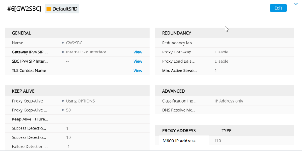
the GW to SBC interface passes back the ISDN signalling back to the SBC when the communication has to go the other way the IP group for GW2SBC is shown below
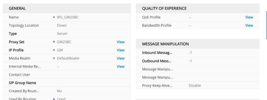
The IP group looks like
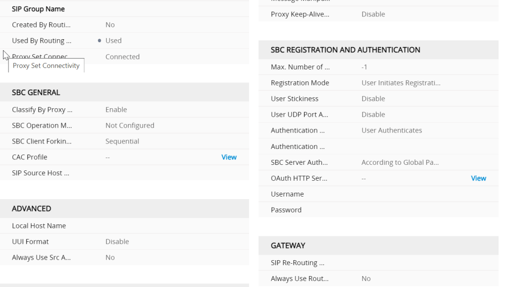
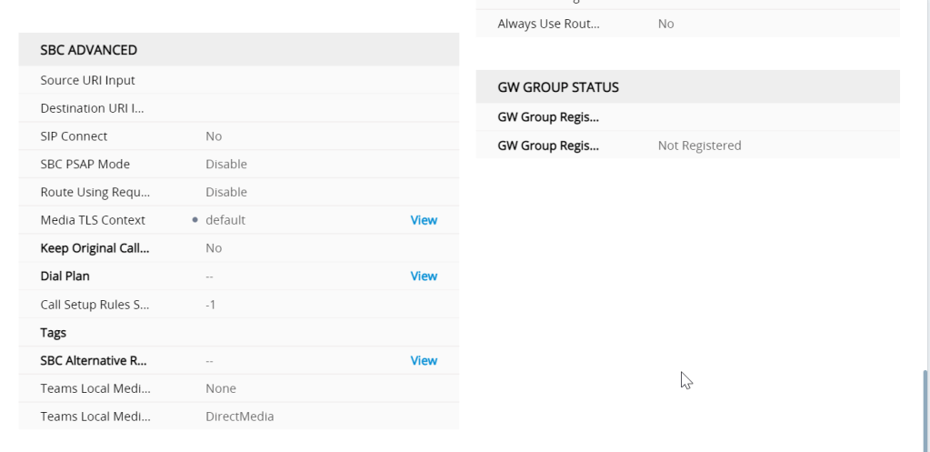
One of the most imortant settings here is the used by routing server setting (ARM) without this it wont work
IP group SBC2 GW 2
classified by proxy this feels like a control
whats is classification ?
Classification is the process in which the AudioCodes gateway or SBC uses to associate the source of a SIP dialog request with a IP Group. By associating the source of the call with a defined IP Group entity, the SBC can then use this association to determine how the call will be processed. The classification rules cannot only be used to define the source of the SIP request for routing/manipulation purposes, but it canalso be used to block unwanted call attempts.
How does AudioCodes classify incoming calls?
AudioCodes uses three stages when attempting to classify an incoming SIP dialog request.
The first stage is to attempt to classify the SIP dialog by first comparing if the source of the request already exists in the device’s registration database.
If the device is not found in the AOR/registration database, the source can then be compared against the defined IP Address/ports used in the ProxySets table. If the source is found to be a match with one of the defined ProxySet entries, the call will be then associated with the source IPGroup which uses that ProxySet. This option can be enabled through the “Classify by Proxy Set” definition found in the IPGroup table definition.
Finally, if the call does not match either the registration database or the definitions in the ProxySet table, the AudioCodes device will attempt to match the source by comparing the SIP request with the criteria defined in the Classification Table.
Are some classification options better than others?
For security purposes, it is recommended to use the Classification rules as defined in the Classification Table, as the Classification Rules allows the user to define additional SIP message characteristics that can be used to increase the strictness and security of the classification process. Classifying the SIP request source by the Proxy Set is allowed but is only recommended if the IP address of the IP Group is unknown or is configured with a FQDN.
M800 GW2SBC Advanced properties
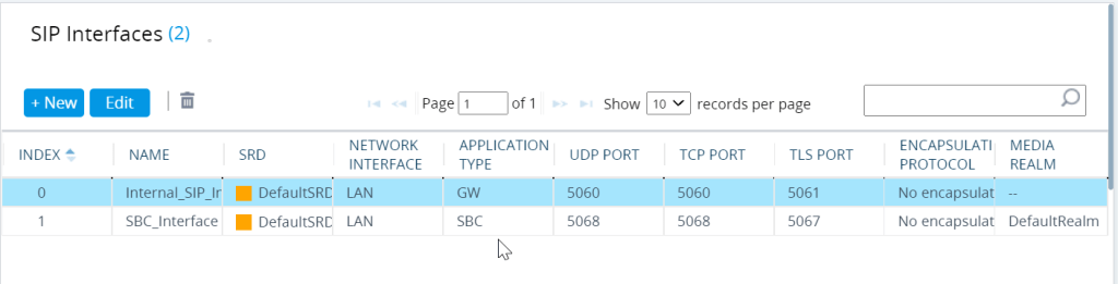
SIP interfaces
covered in other parts of the blog but i am going to do a quick primer here
we add a 2nd SIP int when we want to get our SBC on
the Internal SIP is the GW application and the SBC interface is for the SBC (application type)
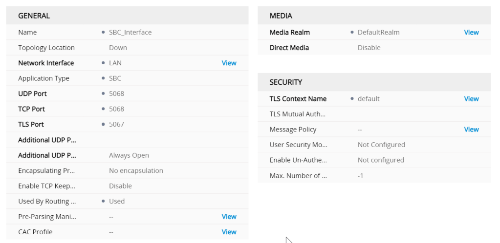
SBC IP interface
the proxy set and IP groups defines the signalling interfaces and ports needed to go from GW to SBC and SBC back to GW to punch the media back to the E1
Though the actual properties of an interface is defined in the profile , if there are tweaks to be made to get something to work the profile seesm to be the place
My question would be where the profile for the SBC
ARM basically controls the profile back to the regional and the GW controls the E1
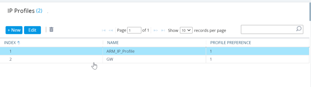
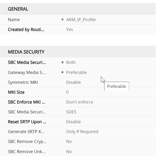
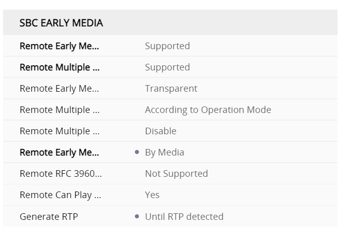
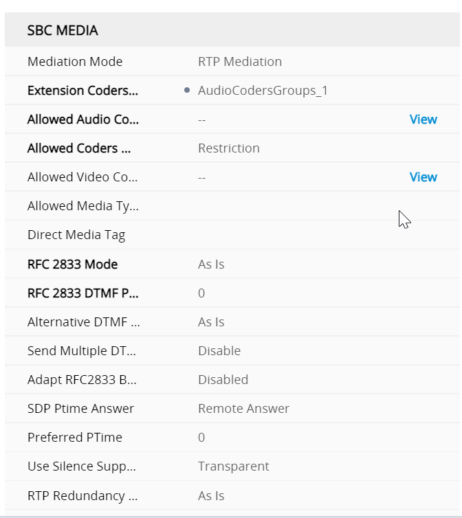
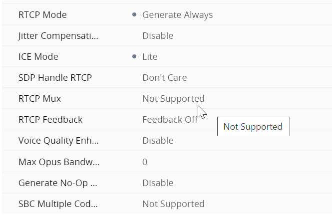
IP profiles are quite meaty configs Regional ARM profile
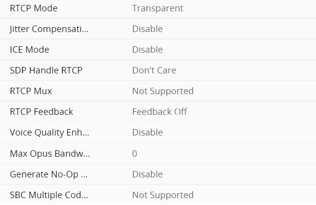
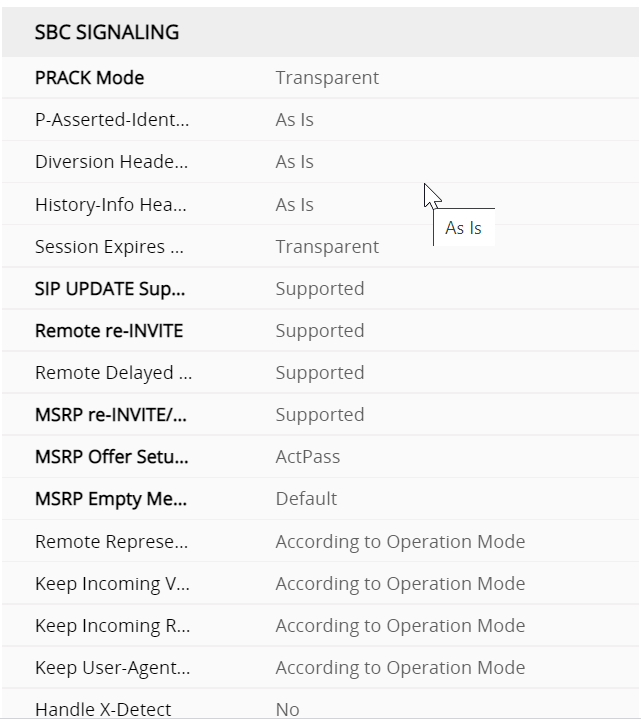
SBC signalling ARM profile regional
Part 1 of the SBC signalling properties
so whats the Profile for the GW interface look like
so whats the profile for the gateway look like ?
Gateway genrarl IP profile
The first difference is that it isnt created by the routing server
Gateway Profile SBC signalling M800
under the profiles this defines what gets translated from the SBC interface to the gateway
Desiging DMO SBC routing environments
This comes down to good IP management i mean , the bible is here
External trusted IPs are the Internet external IPs of the enterprise network. These IP’s are the IP addresses used by Microsoft Teams clients when they connect to Microsoft 365. You need to add these external IPs for each site where you have users using Local Media Optimization.
so this should be an easy check by using a get instead
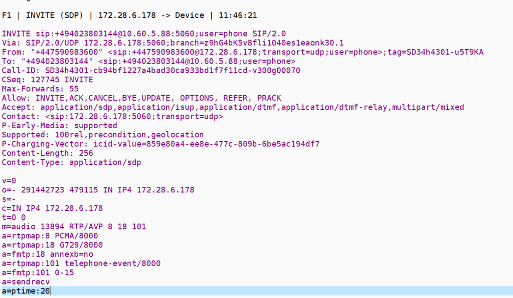
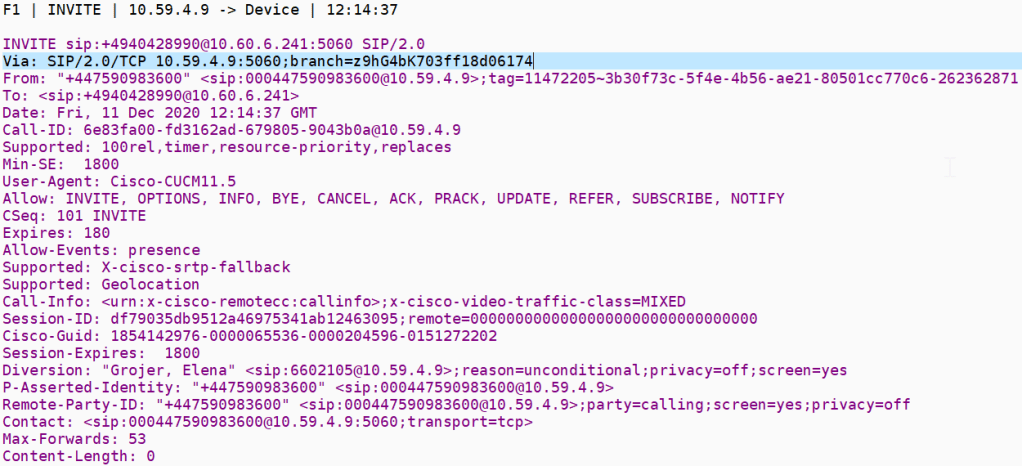
I am currently trying to solve a call forward issue in a SIP cloud all call forward or SIP redirection call flows have two legs
The inbound Invite to the forwarded SIP endpoint
The outbound Invite with a Diversion header
Where we must cross an SBC we have number plan dependencies – SIP trunk providers will only accept diversion headers in a specific number format, which also must be part of the extension range for the device
If you stray from the defined number plan -you may get a reject from the SIP trunk provider this is going to be in the format in one of the following headers in the outbound invite
1.Diversion header format and some screening indications
2.P asserted identity PAI
3.Remote party ID with some screening indications
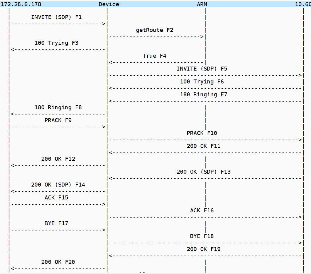
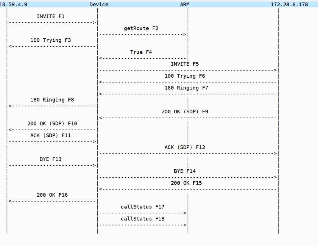
its important to realize that its a single call flow with two legs -that stay up – like all cloud UC offerings there is a web API call in the midst of the SIP signaling
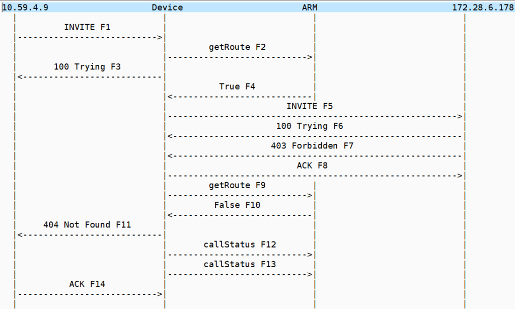
The call flow is a bit of a shell game the headers swap values to make the call forward work and the way the architecture is such that the inbound and outbound invites are processed on separate SBC both legs have got to stay in state for the forward to work
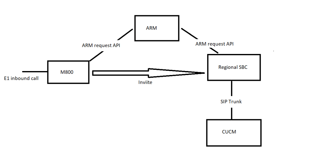
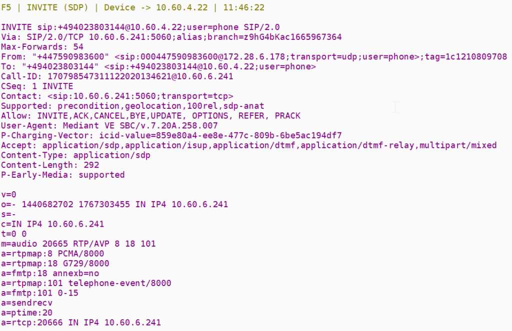
MSP Invites the SBC
SBC makes an API call to ARM
SBC sends invite to IP PBX
At this point the IP PBX is building the outbound invite with the diversion header which will invite the SBC again which in turn makes another API call which will then get the SBC to invite back to the MSP
The 180 that gets generated is actually from the call forward via the 2nd leg
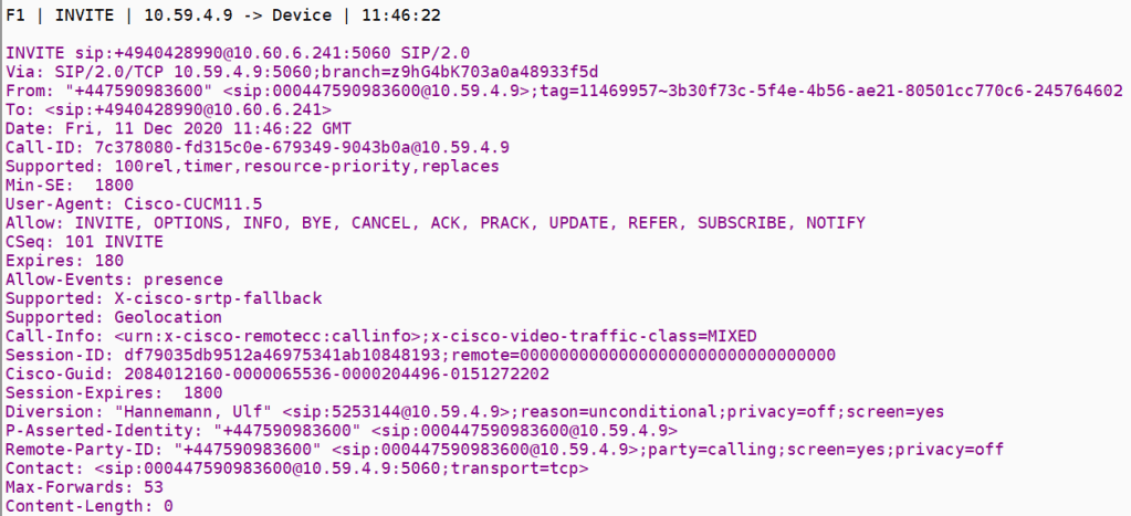
The inbound invite doesn’t need a registered endpoint the CUCM is going to generate the new outbound invite because of the existence of the diversion header , the software will build the invite basically to the call forward and send the diversion header back to the MSP trunk
The remote party here in this outbound invite is the original inbound invite calling party we send this back to the MSP so it can connect the calls
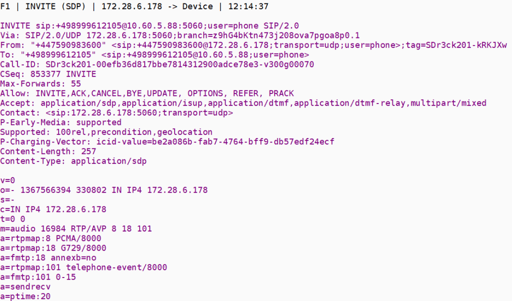
Inbound invite
Inbound invite ladder tableJust to set one end of the shell game from the MSP
after the ARM API
SIP re invitation to the SIP UA in the enterprise
Outbound invite
This is where we see how the SIP UA has modified the inbound invite
The first shell of the call forward
the invite is shown below – the SBC is using a delayed offer for SDP the diversion header itself isn’t really used since its just a redirect flag but MSP use it to control SIP redirection
after the ARM API
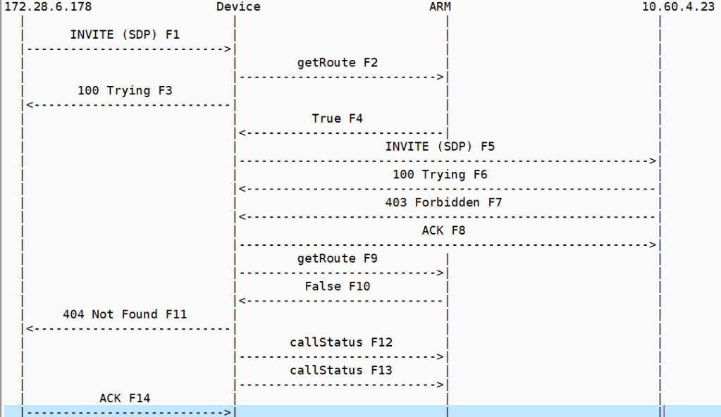
when it all goes wrong
This is an example of a call forward that doesn’t work when something has changed in the configuration
inbound invite
but remember that these two legs set each other up so there are two possibilities here
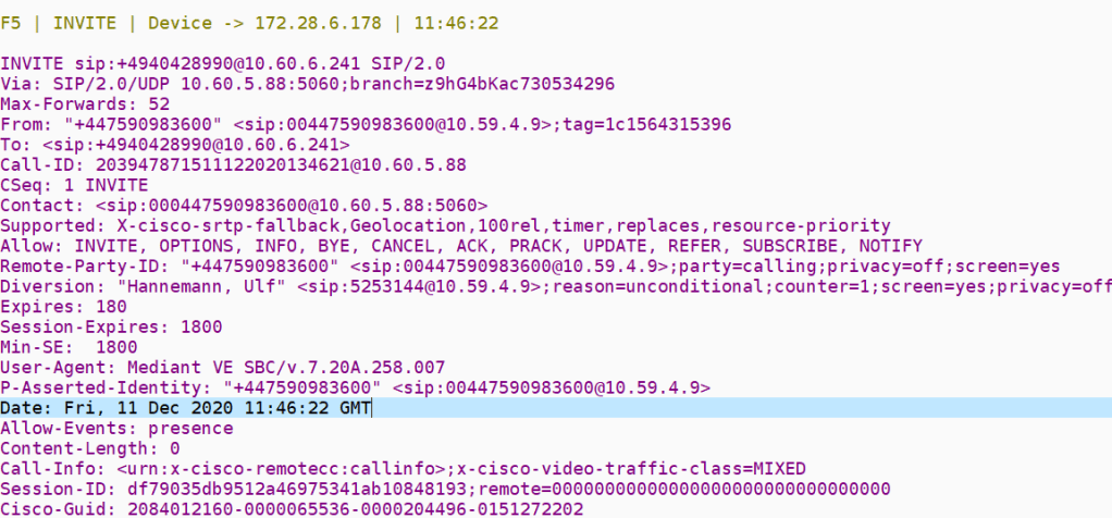
There is something about the invite that is getting forbidden hence if this is the case all we would need to analyze is the f5 invite from both flows to see the differences
The forbidden is being triggered by the outbound invite with the diversion header and extra fields and this proxies back to the inbound invite so the 403 in the outbound just proxies back to the 403 in the inbound leg
outbound invite
For this failure we need to investigate why the MSP rejects with Forbidden
MSP database routing
MSP will authenticate calls depending on what is configured in their routing database. We also need to make a few definitions about the number formats
Private Number (rnx-ext)
E164
534-6404
44-156478-6404
an example of PNP vs +CC
MSP has stated that routing database authenticate is based on 2 points
Diversion header is presented – should be +CCxxx or private number configured on the MSP side
From header should be +CCxxx or private number configured on the MSP side
so in the case for the above extension 6404 has a call forward to 447795642799 the diversion header is shown below
534-6404 is the private number of 44-156478-6404 so the call is authenticated from the site
so in the case of the failure seen at RNX 660 the PNP was not configured on the OBS side , so we where sending the diversion header in the right format
Steel mountain Data centre- protected by Network ACLs
ACL controls what can establish a TCP/IP socket connection to specific ports which means ACLS control what services you can get to on a network
ACL Nut
ACLS have a mask which determines what gets passed and what gets dropped
They use an inverse mask , an example of this is 0.0.0.255 , where ever there is a 0 you must consider the network address wherever there is a 1 you can ignore it so the inverse of a normal mask
for example if you got an ACL that looks like this
10.1.1.00.0.0.255
the network address to be processed is 10.1.1.0 in binary is
00001010 .00000001.00000001.00000000
and the mask in binary is
00000000.00000000.00000000.11111111
0 indicates that the network address must be considered (exact match)
1 in the mask is a don’t care
10.1.1.”we don’t care what’s in this last octet since here it is all ones “so the address we process starts with 10.1.1.1 and stops with 10.1.1.255
you can subtract the normal mask from 255.255.255.255 to get the inverse mask
255.255.255.255-255.255.255.0 = 0.0.0.255
ACL cuts
source 0.0.0.0 / wildcard 255.255.255.255 means “any ” how so ?? because basically we are flying all 1’s against 0.0.0.0 it can be any value between 0 and 255 so that’s pretty much everything
if we got a source/wildcard 10.1.1.2/0.0.0.0 that means we got to match exactly in every position so that means the same as host 10.1.1.2
192.168.32.0/24 (192.168.32.0 – 192.168.32.255)
192.168.33.0/24 (192.168.33.0-192.168.33.255)
192.168.34.0/24 you get the idea
192.168.35.0/24
192.168.36.0/24
192.168.37.0/24
192.168.38.0/24
192.168.39.0/24
in these addresses the first two octets and the last octet is the same for each of these networks
Decimal
128
64
32
16
8
4
2
1
32
0
0
1
0
0
0
0
0
33
0
0
1
0
0
0
0
1
34
0
0
1
0
0
0
1
0
35
0
0
1
0
0
0
1
1
36
0
0
1
0
0
1
0
0
37
0
0
1
0
0
1
0
1
38
0
0
1
0
0
1
1
0
39
0
0
1
0
0
1
1
1
The first five bits match that is to say there is no differences in these columns
This means that those 8 original networks can be summarized as one
If you look at the anatomy of a network acl or NACL it looks a bit like this
access-list 10 permit 192.168.146.0 0.0.1.255
this permits traffic from 192.168.146.0 – 192.168.147.254
access-list 11 permit 192.168.148.0 0.0.1.255
this permits traffic from 192.168.148.0-192.168.149.254
How ACLS are processed
Traffic that comes into a router via an interface is compared to the ACL entries based on the order that they have been configured in , so they run from the top ACL statements to the last ACL statement of an access-list
new statements are added to the end of the list
The router will process network traffic until it gets to the end of the list , this traffic would be denied ( since no match in the configured ACL)
“There is an implied deny for traffic that is not permitted”
for this reason you should have the frequently hit entries at the top of the list
A single ACL entry with only 1 deny has the effect of denying all traffic , you must have at least one permit statement
these two ACLS have the same effect
access-list 101 permit ip 10.1.1.0 0.0.0.255 172.16.1.0 0.0.0.255
!--- This command is used to permit IP traffic from 10.1.1.0 !--- network to 172.16.1.0 network. All packets with a source !--- address not in this range will be rejected.
access-list 102 permit ip 10.1.1.0 0.0.0.255 172.16.1.0 0.0.0.255
access-list 102 deny ip any any
!--- This command is used to permit IP traffic from 10.1.1.0 !--- network to 172.16.1.0 network. All packets with a source !--- address not in this range will be rejected.
In this example, the last entry is sufficient. You do not need the first three entries because TCP includes Telnet, and IP includes TCP, User Datagram Protocol (UDP), and Internet Control Message Protocol (ICMP).
!--- This command is used to permit Telnet traffic !--- from machine 10.1.1.2 to machine 172.16.1.1.

access-list 101 permit tcp host 10.1.1.2 host 172.16.1.1 eq telnet
!--- This command is used to permit tcp traffic from !--- 10.1.1.2 host machine to 172.16.1.1 host machine.

access-list 101 permit tcp host 10.1.1.2 host 172.16.1.1
!--- This command is used to permit udp traffic from !--- 10.1.1.2 host machine to 172.16.1.1 host machine.

access-list 101 permit udp host 10.1.1.2 host 172.16.1.1
!--- This command is used to permit ip traffic from !--- 10.1.1.0 network to 172.16.1.10 network.

access-list 101 permit ip 10.1.1.0 0.0.0.255 172.16.1.0 0.0.0.255
you can use ports and traffic types in ACLS , which is where we can control what the IP networks can access so for example
It is a good practice to apply the ACL on the interface closest to the source of the traffic. As shown in this example, when you try to block traffic from source to destination, you can apply an inbound ACL to E0 on router A instead of an outbound list to E1 on router C. An access-list has a deny ip any any implicitly at the end of any access-list.
DHCP and ACL’s
If traffic is related to a DHCP request and if it is not explicitly permitted, the traffic is dropped because when you look at DHCP request in IP, the source address is s=0.0.0.0 (Ethernet1/0), d=255.255.255.255, len 604, rcvd 2 UDP src=68, dst=67.
Note that the source IP address is 0.0.0.0 and destination address is 255.255.255.255. Source port is 68 and destination 67. Hence,
you should permit this kind of traffic in your access-list else the traffic is dropped due to implicit deny at the end of the statement.
The motor way analogy
Traffic on a IP network is a bit like traffic on a road network and much like those meanings where you get inbound and outbound in response to road blocks for example the same sorts of meanings occur
Out—Traffic that has already been through the router and leaves the interface. The source is where it has been, on the other side of the router, and the destination is where it goes.
In—Traffic that arrives on the interface and then goes through the router. The source is where it has been and the destination is where it goes, on the other side of the router.
Inbound —If the access list is inbound, when the router receives a packet, the Cisco IOS software checks the criteria statements of the access list for a match. If the packet is permitted, the software continues to process the packet. If the packet is denied, the software discards the packet.
Outbound—If the access list is outbound, after the software receives and routes a packet to the outbound interface, the software checks the criteria statements of the access list for a match. If the packet is permitted, the software transmits the packet. If the packet is denied, the software discards the packet.
EDITING ACL’s
so this is in bold because there are some rules here that i was not aware and i have fallen foul of
rule 1 – when you edit an ACL entry and delete a specific line from an ACL the whole ACL is deleted
so whenever you are working with an ACL you should take the trouble to make a note of what was there in the first place make the change you need in the editor and then re-apply it
rule 2 – if you are working with a numbered ACL list , if in your edit you attach a number than it will find its place in the ACL
DEBUGGING ACL’s
Use the debug ip packet 101 or debug ip packet 101 detail command in order to begin the debug process.
ACL types
standard;
This is the command syntax format of a standard ACL.
Free switch (fs) is basically open source software defined technology stack that supports the following endpoints and is a class 5 soft switch , IVR platform and high quality conference resource and supports principally SIP but also Google talk and Skype
Module Types FS
The following modules comprise the FS IP PBX
Endpoint for talking to VOIP , PSTN , Google Talk , Skype etc
Application there are hundreds of application modules for conferencing , voicemail , IVR that are contained in the tools module
Dialplan responsible for routing calls based on call context information such as caller ID , the default dialplan module is in the XML dialplan
Directory provides logins and configurations that users can register with FS
Codecs that are used for the encoding of media streams
File Formats play audio files whose common common formats are supported by the sndfiles module which is included by default
Loggers records log messages such as log file.xml_cdr
Languages languages that are supported for scripting javascript is supported
Configuration files in FS
All configuration files are written in XML the default configuration that comes with the virtual machine is located in /etc/freeswitch
One of the first differences that is evident between Cisco unified call manager and FS is that FS has inbuilt support for SMS under the chatplan whereas in the Cisco framework you would have to provision load of middle ware and somewhere would be a node.js app but thats a story for another day
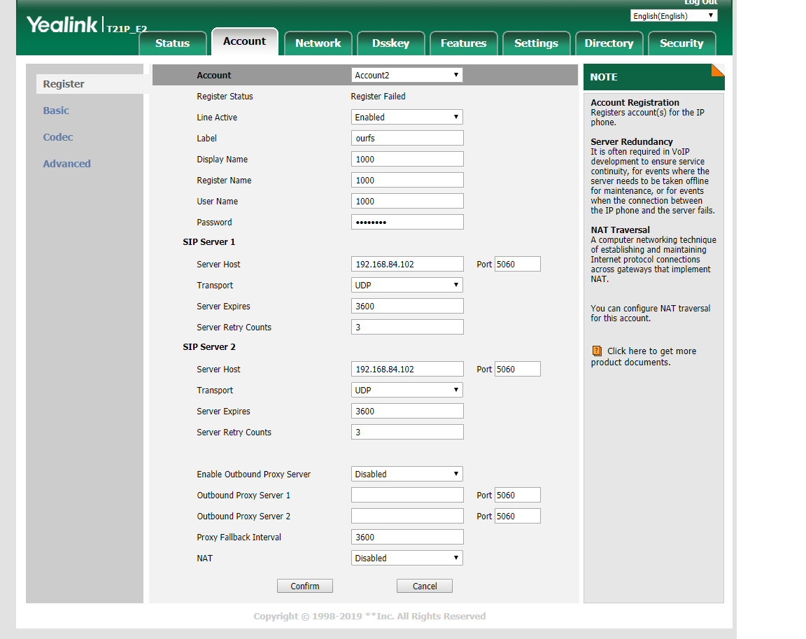
How to register Yealink T21 to FS
Head over to the default directory it will look like this one below , these are all the extensions in the default context which is like the CUCM internal partition
but will end up like this
<include>
<user id=”1000″>
<params>
<param name=”1000″ value=”1000″/>
<param name=”vm-password” value=”1000″/>
</params>
<variables>
<variable name=”toll_allow” value=”domestic,international,local”/>
<variable name=”accountcode” value=”1000″/>
<variable name=”user_context” value=”default”/>
<variable name=”effective_caller_id_name” value=”Extension 1000″/>
<variable name=”effective_caller_id_number” value=”1000″/>
<variable name=”outbound_caller_id_name” value=”$${outbound_caller_name}”$
<variable name=”outbound_caller_id_number” value=”$${outbound_caller_id}”$
<variable name=”callgroup” value=”techsupport”/>
</variables>
</user>
</include>
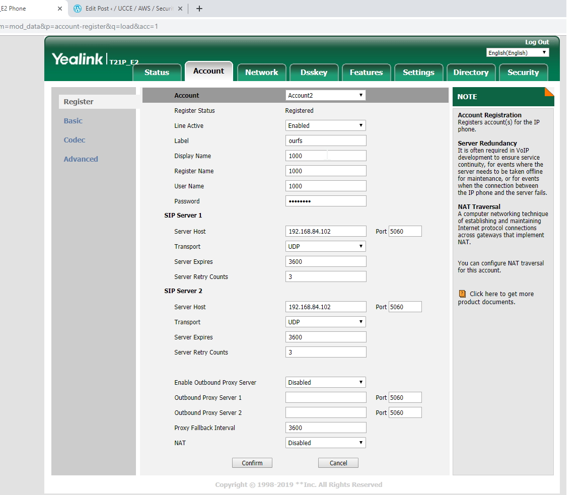
then it will register to the fs
The most important concept in FS is ………
the basic construct is a dialplan which is simply a list of actions which is controlled by the digits dialled , a dialplan can be broken into contexts where each context is a group of extensions , each of which contains specific actions can be performed on the call
the dialplan processor uses regular expressions which is a pattern matching system to determine which extensions and actions to execute
<action application =”log” data=”INFO dialed number is [$1]”/>
This captures the digits dialed and matches them against 10\d\d so this is a range 1000 to 1099 , so if a user dials 1050 this would execute the application called log and print out the digits dialed to the screen , the value $1 would be interpolated or expanded
FS has 3 main contexts
default
public
features
The default context
This can be though of as the internal as it services users who are directly connected to FS
There are some typical PABX type extensions contained within conf/dialplan/default.xml the local extension does many things
routes calls between internal users
sends calls to the destination users voicemail on a no answer condition
enables in call features with bind_meta_app
updates the local calls data base
The local extension
<extension name=”Local_Extension”> <condition field=”destination_number” expression=”^(10[01][0-9])$”> <action application=”export” data=”dialed_extension=$1″/> <!– bind_meta_app can have these args <key> [a|b|ab] [a|b|o|s] <app> –> <action application=”bind_meta_app” data=”1 b s execute_extension::dx XML features”/> <action application=”bind_meta_app” data=”2 b s record_session::$${recordings_dir}/${caller_id_number}.${strftime(%Y-%m-%d-%H-%M-%S)}.wav”/> <action application=”bind_meta_app” data=”3 b s execute_extension::cf XML features”/> <action application=”bind_meta_app” data=”4 b s execute_extension::att_xfer XML features”/> <action application=”set” data=”ringback=${us-ring}”/> <action application=”set” data=”transfer_ringback=$${hold_music}”/> <action application=”set” data=”call_timeout=30″/> <!– <action application=”set” data=”sip_exclude_contact=${network_addr}”/> –> <action application=”set” data=”hangup_after_bridge=true”/> <!–<action application=”set” data=”continue_on_fail=NORMAL_TEMPORARY_FAILURE,USER_BUSY,NO_ANSWER,TIMEOUT,NO_ROUTE_DESTINATION”/> –> <action application=”set” data=”continue_on_fail=true”/> <action application=”hash” data=”insert/${domain_name}-call_return/${dialed_extension}/${caller_id_number}”/> <action application=”hash” data=”insert/${domain_name}-last_dial_ext/${dialed_extension}/${uuid}”/> <action application=”set” data=”called_party_callgroup=${user_data(${dialed_extension}@${domain_name} var callgroup)}”/> <action application=”hash” data=”insert/${domain_name}-last_dial_ext/${called_party_callgroup}/${uuid}”/> <action application=”hash” data=”insert/${domain_name}-last_dial_ext/global/${uuid}”/> <!–<action application=”export” data=”nolocal:rtp_secure_media=${user_data(${dialed_extension}@${domain_name} var rtp_secure_media)}”/>–> <action application=”hash” data=”insert/${domain_name}-last_dial/${called_party_callgroup}/${uuid}”/> <action application=”bridge” data=”user/${dialed_extension}@${domain_name}”/> <action application=”answer”/> <action application=”sleep” data=”1000″/> <action application=”bridge” data=”loopback/app=voicemail:default ${domain_name} ${dialed_extension}”/> </condition> </extension>
Compute is a measure of the computational power to fulfill your workload , EC2 allows you to acquire compute via images or virtual servers called instances
Instance types
The instance type defines the virtual hardware supporting the EC2 instance , they vary in the following dimensions
vCPU
Memmory
Storage ( size and type)
Network performance
The instance types are optimized as below
c4
Compute optimized
r3
Memmory optimised
i2
Storage optimised
g2
Graphics optimised
Enhanced networking
Some instance types support enhanced networking for greater network performance , it reduces the impact of virtualization on networking by enabling a capability called single root I/O virtualization SR-IOV , this gives more packets per second , less latency this will be picked up in VPC
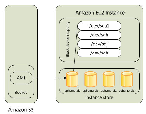
AMI
The amazon machine image AMI is similar to an VM . OVA template , in as such it is a software definition at launch it defines
OS and configuration
Initial state and patching
Application and system software
There are four sources of AMI’s
Published by AWS
AWS marketplace
Generated from existing licenses generate an image from an existing EC2 container
Uploaded virtual servers use AWS VM import export service ,raw,VHD ,VMDK and OVA
Addressing an instance
There are several ways an instance can be addressed
Public DNS name when you launch an instance AWS creates a public DNS name and cannot be specified by the enterprise
Public IP the launched instance will have a public IP address from a pool reserved by AWS, it only persists while the instance is running
Elastic IP is an address that you can reserve and use for your instance from a pool.It is a public IP address , which persists until the customer releases it and is not tied to the instance
Initial access
EC2 uses public key cryptography to encrypt and decrypt login information
Virtual firewall protection
AWS controls traffic in and out of the instance via a virtual firewall called a security group , which allow you to control traffic based on
Below are the security group attributes
Port
Protocol
source/destination identifies the far end of the communication , can be identified by CIDR block x.x.x.x/subnet or a security group
Security groups have different abilities based on their association with VPC or with EC2
Type of security group
capability
EC2
Control outgoing instance traffic
VPC security groups
Outgoing and incoming security groups
every instance must have at least one security group, but can have more
A security group is a default deny that is to say it will not allow any traffic that is not explicitly defined by a security group rule
In a case of multiple security groups , the aggregate of the groups is the rule , so if you allow RDP from x.x.x.x and HTTP from 0.0.0.0/0 in two different rules , than the EC2 instance will get both RDP traffic and HTTP traffic
A security group is a stateful firewall , so that ports can fix up, they are applied at the instance level rather than the perimeter
Instance lifecycle
One of the benefits of AWS Ec2 is the ability to bootstrap , that is the ability to run code when the instance is launched
One of the parameters when an instance is launched is a string value called UserData , this string is passed to the OS at launch to be executed as part of the launch , on linux this can be part of a shell script, on windows this can be a powershell script it can do the following
Apply a patch
Enrol a directory service
Install application software
VM import /export
This allows you to import virtual machines from your enterprise ,you cannot export an AMI
Instance metadata
You can use instance metadata to control your instance , you can make a callto the OS without making a call to the AWS API , an HTTP call to http://169.254.169.254/latest/meta-data/ will return the top node of the metadata tree ,some of the attributes are shown below
Security group ids associated with the the instance
Instance id
Instance type
AMI used to launch the instance
There is a lot more ! see documentation
Managing instances
When the number of instances starts to climb you can use tags to manage them , as you can with other AWS services , you apply ten tags per instance. Monitoring instances is done via Amazon cloud watch.
Pricing instances
You are charged for EC2 instances while they are in a running state, but the amount you are charged depends on the following 3 pricing options
On demand instances
Price per hour on AWS website Most flexible pricing option since the enterprise controls when the instance is running Least cost effective price per hour of the three options
Reserved instances
Make capacity reservation for predictable workloads Can save up to 75% over the on demand hourly rate To reserve enterprise needs instant type and availability zone and the duration of the reservation Two factors determine the cost the commitment and the payment option Commitment is the duration of the reservation, can be one or three years , the longer the commitment the bigger the discount Payment options are All upfrontPartial upfrontNo upfront
Spot instances
For workloads that are not time critical and tolerant of interruption. The enterprise specifies a bid price, if the bid price is above the spot price , the enterprise gets the instance Instance will run until
Customer terminates
Spot price goes above the bid
Not enough unused unused capacity to meet the demand for spot instances
If AWS needs to terminate they will send a two minute termination warning
Architectures with different pricing models -EXAM !!!!!
So depending on the need you can have different pricing models per architecture
Website that does Christmas foods gets 20,000 hits per day in December , but at other times gets only 5000 hits per day so you could go on demand pricing for December , but then use reserved instances pricing off peak
Tenancy options
the following tenancy options can help a client achieve security and compliance goals
Shared tenancy
This is the default tenancy model for all EC2 instances , so this basically means that in the AWS data center your sharing a blade with other customers
Dedicated instances
dedicated instances run on hardware that is dedicated to a single customer
Dedicated host
the physical server is dedicated to the instance, this can help meet licensing requirements . This differs from dedicated instances which can launch on any hardware dedicated to the account
Placement groups
A placement group is a logical grouping of instances within an availability zone , so chatty applications that need to talk to each other can do so with low latency 10 Gbps network, remember to exploit this you need to choose an instance type that supports advanced networking
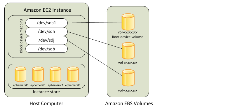
Instance stores
provide temporary block storage for your instance , is physically attached to your server and is ideal for storing data that changes frequently . The keys aspect of instance stores is that they are temporary data in the instance store is lost when
underlying disk drive fails
the instance stops (data persists on reboot)
instance terminates
Elastic block store
The limited persistence of block stores means that they are ill suited for more durable workloads, to get around this problem AWS uses Elastic Block Store , whose volume is automatically replicated within its availability zone . Multiple block stores can be added to an instance
Types of EBS volumes
There are several different types
Magnetic volumes
these have the lowest performance , and the lowest cost , they range in size from 1 GB to 1 TB and average 100 IOPS , but can burst to hundreds of IOPS they are best used for
work loads where data is accessed infrequently
sequential reads
low cost is required
they are billed on size of disk not what is stored on them
General purpose SSD
Suitable for a wide range of work loads , they size from 1 GB to 16 GB and provided 3 IOPS per GB provisioned which is capped at 10,000 IOPS, so a 1 TB volume will provide 3,000 IOPS , a 5 TB volume wont give you 15000 IOPS because of the cap.They are suited for a wide range of work loads such as
system boot volumes
small to medium sized databases
development and test environments
Provisioned IOPS SSD
Designed to meet the needs of I/O intensive work loads , such as database workloads , they are the most expensive work load , they range in size from 4 GB to 16 GB .You can stripe multiple volumes together in a RAID 0 configuration, pricing is based on the size of the volume and the IOPS reserved. they can provide 20000 IOPS and are suitable for
Critical business applications
large database work loads
Protecting Data
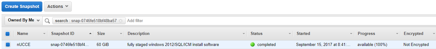
When working with instances you need to be able to perform back up and recovery of EBS volumes via snap shots. They can be taken in the following ways
AWS management console
Through the CLI
Through the API
a schedule of regular snap shots
snapshot is stored on system S3 , hence you need to use the EBS console to manipulate them
Creating a volume from a snapshot
to use the snap shot you create a volume from the snap shot , when you do this the volume is created immediately
Recovering Volumes
Since EBS volumes persist after an instance fails , it is straight forward to detach the volume and attach it to another instance so that the data can be retrieved.
Encryption volumes
when you launch an encrypted volume , amazon uses the KMS ( key management system) to handle the key management via industry standard AES-256 algorithm. The encryption happens on the servers where the volumes are attached
Summary
To launch an instance you must specify an AMI which defines the virtual hardware , memory vCPU etc
spot instances are best for work loads that can tolerate interruption, reserved instances are are best for long term compute needs, on demand instances provide flexible platforms that can scale to need
on demand instances can be used to scale up a web application running on reserved instances in response to a traffic spike.
Enhanced networking enables you to get higher through put , lower jitter and latency
–via public IPv4, elastic IP or public DNS
Data in an instance store is lost when the instance is stopped or terminated , though of course would survive an OS reboot
On demand instances require no up front commitment , and can be launched at any time and are billed by the hour .Reserved instances require an upfront commitment .Spot instances are launched when your bid price exceeds the spot price, spot instances will run until the spot price exceeds your bid price , in which case you get a 2 minute warning .
Every instance type is rated for low medium or high , or 10 Gbps network performance, with larger instance types being rated higher , some instance types are network enhanced.
Metadata is information about an instance , such as instance ID , instance type , and security group, available over HTTP.
Security groups are virtual firewalls that control traffic in and out of your EC2 instance, they deny by default , and you can specify traffic direction , port protocol and destination address via CIDR block, they are stateful meaning that an outgoing rule will allow response without a corresponding incoming rule.
Magnetic volumes provide an average performance of 100 IOPS and can be provisioned up-to 1 TB.They are good for cold and infrequently accessed data .General purpose SSD volumes provide 3 IOPS / GB up to 10,000 IOPS , with smaller volumes able to burst 3000 IOPS . They can be provisioned up to 16 TB
Any volume type can bee encrypted at launch , encryption is built on AWS KMS and is transparent to attached instances
snapshots provide a point in time backup of an EBS volume and is stored in S3 , subsequent backups are incremental and they only store deltas
Thats why its called S3 because of the three S’s,it is basically easy to use object storage, with of course a web front end.You pay only for the storage you use so it is dynamic , so capacity planning is no longer a constraint
Common uses are
Backup and archive for on premise or cloud
Content storage and distribution
Bi data analytics
Static website hosting
Disaster recovery
Storage classes are
General purpose
Infrequent access
Archive
Glacier is another storage service ,but it is optimised for Data archiving and long term backup, good for “cold data” where a retrieval time of hours is acceptable
Object storage Vs Block / File storage
In traditional IT environments two kinds of storage dominate
Block storage, operates at a low level and manages data as numbered fixed size blocks
File storage operates at a high level (OS) manages data as a hierarchy of files
These two systems would be accessed over a network in the form of a SAN using protocols Fibre Channel , but basically server and OS dependant
S3 is cloud based object storage , it is server independent and is accessed over the internet , data is managed via standard HTTP verbs
Each S3 bucket contains
Data
MetaData
Objects reside in containers called buckets , they are a simple flat file with no hierarchy in terms of a file system. A bucket can hold an infinite number of objects . You can only GET or PUT an object you cannot mount or open a bucket.S3 objects are automatically replicated within a region.
Buckets
A bucket is a container, and forms the top level namespace in S3
AWS Regions
Even though the name for a bucket is global, the bucket is created in the region that you choose, so you can control where your data is stored.
Objects
They are the entries that are actually stored in the S3 bucket. Data is the actual file itself, and Metadata is data about the file.The data portion is opaque to S3 , it doesn’t care about the actual data itself .The metadata of the object is a set of name/value pairs that describes the object.
Metadata breaks down into
System metadata this is used by S3 eg date last modified, size , MD5 digest and HTTP content-Type
User metadata created when the object is created , you can tag Data with something meaningful
Keys
Every object in a bucket is identified by a unique identifier, it called a key it can be up to 1024 bytes of UTF 8, you can have the same key across two buckets but you cannot have identical keys within the same bucket. Bucket and key create a UID
Object URL
S3 is internet based storage and hence has an associated URL
You interact with S3 via higher level interfaces rather than the REST direct these are
AWS SDK
JavaScript
Java
.NET
Node.js
PHP
Python
Ruby
Go
C++
AWS CLI
AWS Management console
Durability and Availability
Durability = 99.99999999%
Availability = 99.99%
Availability is achieved by device redundancy/ multiple devices within a region. Though this can lead to data consistency issues , since it takes time for updates to propagate to all new devices
Access control
To give access of a bucket to others
Coarse grained access controls S3 ACL’s (READ, WRITE FULL-CONTROL at object or bucket level (legacy)
Fine grained access controls , S3 bucket policy , AWS IAM policy and query string manipulation, this is the recommended access control mechanism
Bucket policies include an explicit reference to the IAM principal in the policy, which can be associated with a different AWS account.Using bucket policy you can also specify from where the S3 is accessed eg IP address and also at a particular time of day.
Static Website Hosting
This is a very common use for S3 , if there is no server side scripting required (PHP,ASP.NET or JSP). Because an S3 bucket has an URL it’s easy to change it into a website.
Create a bucket with the same name as the desired website hostname
Upload static files to the bucket
Make all files public (world readable)
Enable static website hosting for the bucket.This includes specifying an index document and an error document
The website will now be available at the S£ website URL <bucket-name>.s3-website-<AWS-region>.amazonaws.com
Create a friendly DNS name in your own domain using DNS CNAME or Amazon Route 53 alias that resolves to the amazon website URL
The website will now be available at your website domain name
Prefixes and Delimiters
This provides a way to access objects in a bucket with hierarchy for example you may want to save some server logs by
log/2016/january/server 42.log
log/2016/february/server 42.log
All of the access methods (including AWS console) support the use of delimiters as above . This technique used in conjunction with bucket policy allow you to control access at the user level.
Storage Classes
The range of storage classes are
standard
High durability and availability, low latency with high throughput
Standard infrequent access
Same as standard , but for colder data, eg more long lived , less frequently accessed
Lower GB per month cost than standard, minimum object size is 128KB, minimum duration is 30 days’s so use it for infrequent access for data that is older than 300 days
Reduced redundancy storage
RRS
Lower durability ( 4 nines)
Reduced cost than standard
Glacier
Low cost ,no real time access, retrieval time of several hours
Controlled via S3 API copies to RRS
Object lifecycle management
Data traditionally can be thought of going from left to right
Hot
Frequent access low latency Use S3 standard
Warm
Less frequent
30 days +, use standard IA
Cold
Archive
90 days move to glacier
Deletion
After 3 years delete
You can use S3 lifecycle configuration rules to move data
Encryption
in flight to S3 data is encrypted via HTTPS (to and from S3)
At rest you can use several variations of SSE ( server side encryption) as you write the data to S3 you can use Amazon key management service (KMS) use 256 bit advanced encryption standard (AES)
You can also use CSE (client side encryption) in the enterprise
SSE-S3 (aws managed keys)
Check box encryption where AWS handles the following for S3
Key management
Key protection
Every object is encrypted with a unique key, which in itself is encrypted by a separate master key, which is issued monthly with AWS rotating the keys
SSE-KMS (AWS KMS Keys)
Fully integrated service , where AWS handles key management and protection, but the enterprise manages the keys .It has the following benefits
Separate permissions for using the master key
Auditing see who used your key
Failed attempts from users who did not have the right permission to decrypt
SSE-C(customer provided keys)
Enterprise maintains its own encryption key, but doesn’t manage client side encryption library
Client side encryption
Encrypt on the client side before transmit, you have two options
Use AWS KMS managed customer key
Use client side master key
When using client side the enterprise retains E2E control of the encryption including management of the keys
Versioning
Helps against accidental deletion of data , by keeping multiple versions of object in a bucket . versioning is activated at the bucket level ,once on it cannot be removed.
You can restore an object by referencing the version ID in addition to the bucket ID and object key
MFA delete
In addition to normal security credentials MFA delete requires an authentication code (temporary one time password).it can only be enabled by the root account (key generated by a virtual MFA device )
Pre signed URLs
By default objects are private meaning that only the owner has access,but the owner can create a pre signed url which will allow time limited permission to download object’s .key created using
Owners security credentials
Bucket name
Object key
HTTP method ( GET for download)
Expiration date
Time
Gives good protection against web scrapers
Multipart upload
AWS provides a multipart upload API for larger files .This gives better network utilisation by virtue of parallel transfers , supports pause and resume , and the ability to upload where the original size is unknown
Range GETs
The range of bytes to be downloaded is defined in the HTTP header of the GET , useful if you have poor connectivity and a large object to download
Cross region replication.
Allows replication of new objects in a bucket in one AWS region to another AWS region.Metadata and ACLs associated with the object is alo part of the replication. Versioning must be turned on in both source and destination buckets , and you must use an IAM policy to give S3 permission to replicate .
Commonly used to reduce latency required to access objects .Existing objects in a bucket are not replicated when it’s turned on this is achieved by a separate command
Logging
You can enable S3 access logs to check requests made to the bucket, when you enable you must choose where the logs will be stored , it can be the local bucket or another bucket, its good practice to define a prefix such as your bucket name / logs.They include the following information
Requester account and ip address
Bucket name
Request time
Action (get , put, list)
Response status error code
Event notifications
When actions are taken on an S3 bucket ,event notifications provide a mechanism, where you can perform other actions in response to the change for example transcoding media files once they are uploaded
Notifications are set up at the bucket level , and can be configured via the S3 console , or REST API or by the SDK.
Notifications can be sent through SNS ( simple notification service) or SQS (simple queue service) or delivered to AWS Lambda to invoke lambda functions.
Best practice , patterns , performance
Common pattern is to backup enterprise file storage to an S3 bucket in a hybrid deployment. If you are using S3 ib#n a GET intensive mode , you should use cloudfront as a caching mechanism for the site / Bucket.
Amazon glacier
Low cost archive storage service with a 3-5 hour retrieval time for the data
Archives / vaults
Data is stored in archives and can contain up to 40 TB of data , and you can have an unlimited amount of archives.Vaults are containers for archives, each AWS account can have up to a 1000 vaults, they can be controlled via IAM policies or vault access policies
Data retrieval
You can retreive 5% of your data for free each month
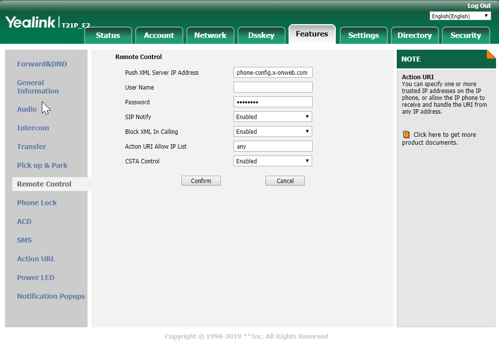
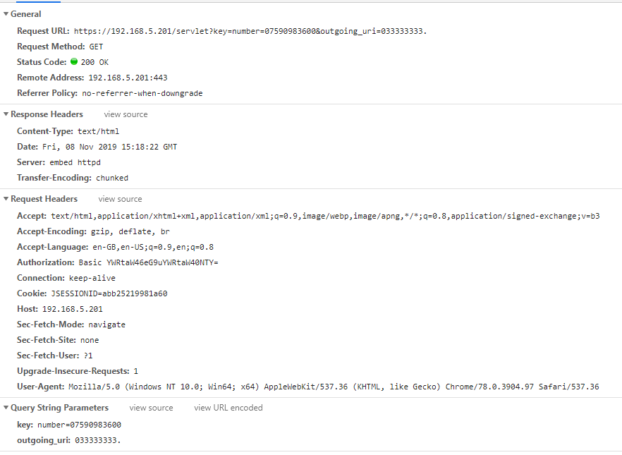
Back in the day it used to be difficult to remote control phones , usually that phone would have to have a CTI layer and you would have to use JTAPI or a java telephony API to send 3rd party call control messages to control
but since phones have become web servers in their own right we can exploit HTTP verbs to control the phone
the set up for this is shown below
Basically we are going to set 2 settings
Action URI Allow IP list – to leave it wide open we can set this to “any” or we can define a sub net here
CSTA Control – set this to enable this is basically ACD protocol speak
once this is set than the phone will go down for a reboot
once it has come back you can issue something like this for the phone
When you send this the browser will use the GET verb to send
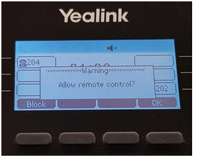
for the first time you send the get the phone will display a message that say do you want to allow remote control , but it only does this the first time , for subsequent requests this will no longer be presented
Laying the foundation to integrate Cisco contact center with AWS connect
This blog covers how to create a UCCE environment hosted on the AWS free tier and is broken down into 3 different stages shown below. I am not building this with a production hat on rather a proof of concept hat on , so the configuration here is not best practice but will get you to Proof of concept quickly.
staging of ICM v 11.0 on EC2 instances in a simplexed architecture within a single availability zone .
staging of ICM v11.0 on EC2 instances with duplexed architecture within a single availability zone
staging of ICM v11.0 on EC2 instances with duplexed architecture using two different availability zones
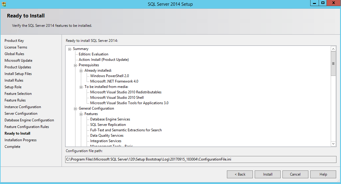
This blog covers the 1st stage which is an ICM v 11 core built as a simplexed progger.
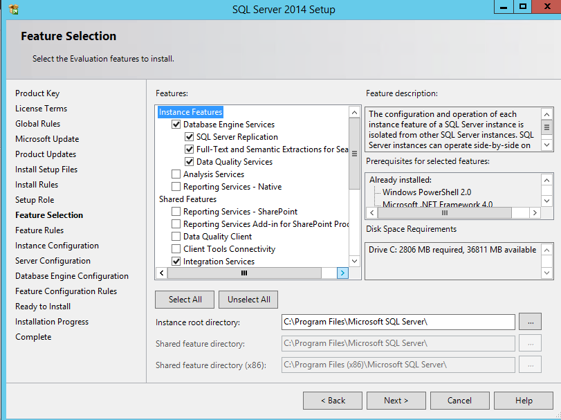
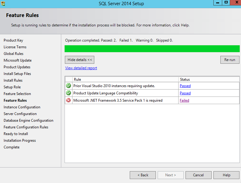
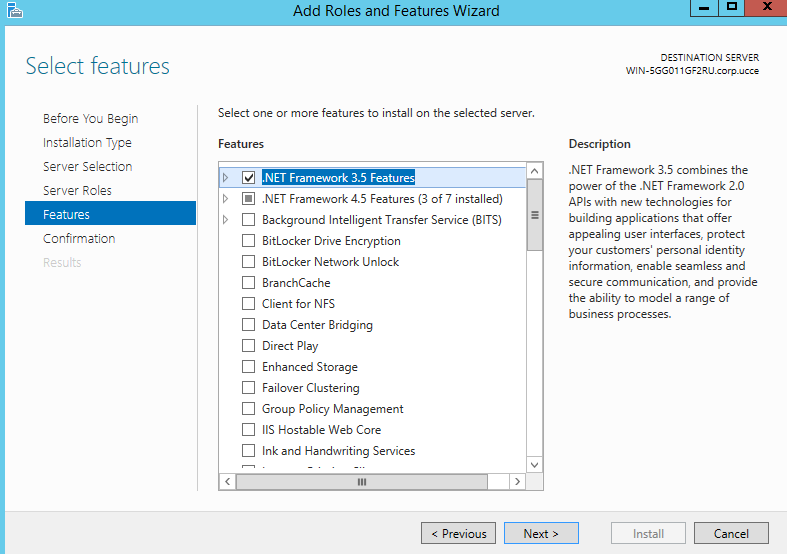
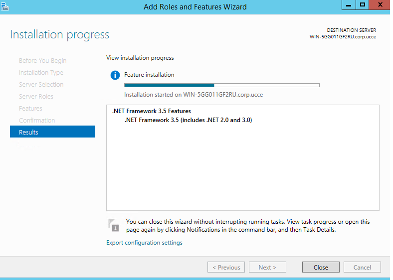
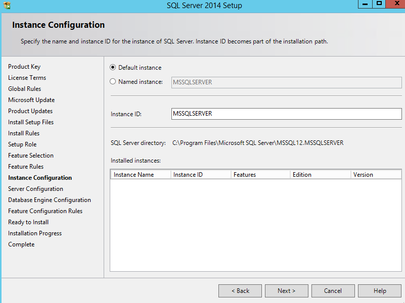
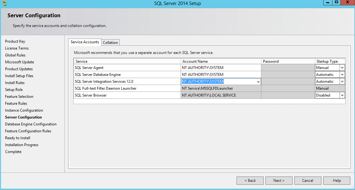
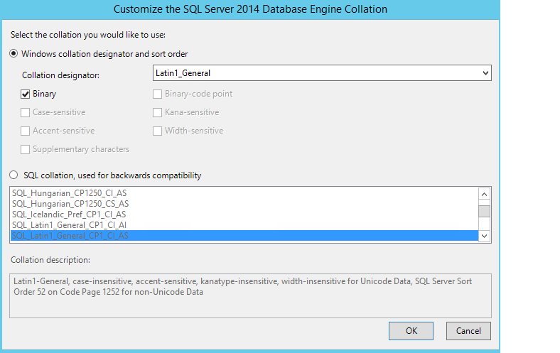
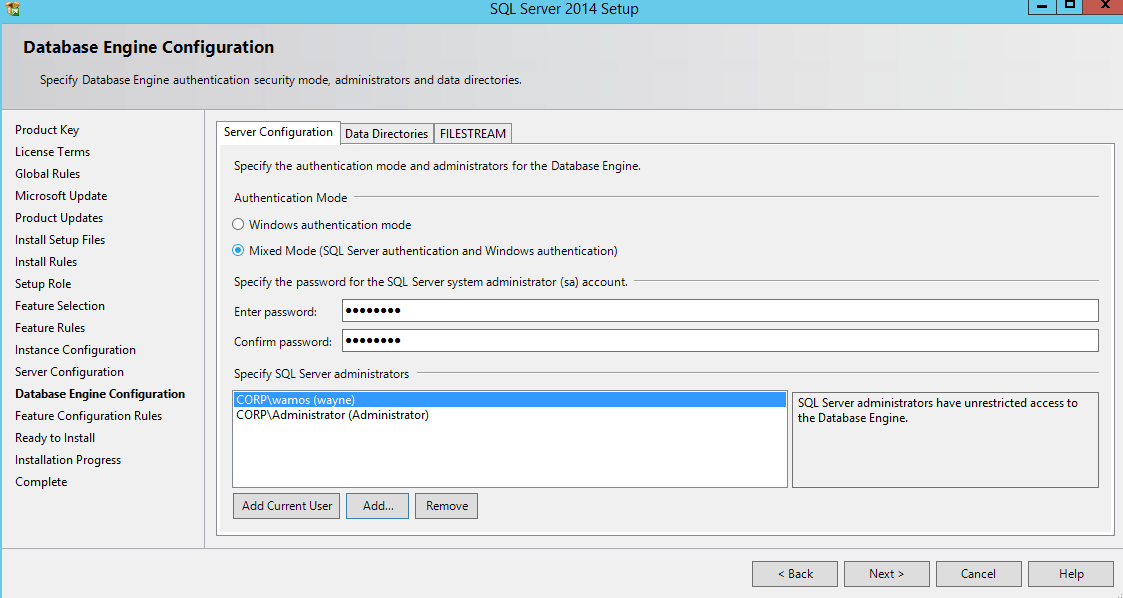
The software platform to be virtualized is an AD integrated windows 2012 R2 / SQL 2014 network (64 bit)
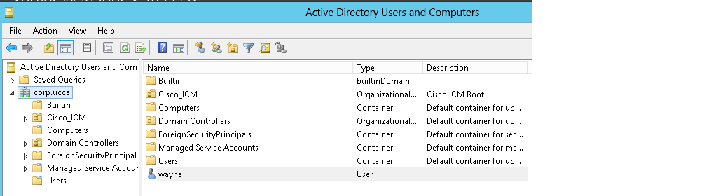
Windows 2012 R2 AD 101
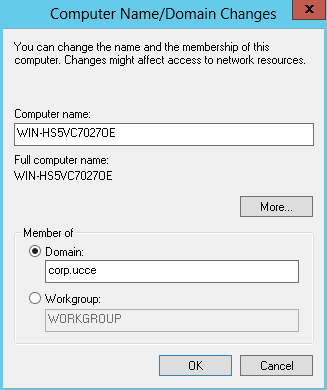
We are going to use the Amazon free tier to create a primary domain controller / EC2 instance To do this boot the Win 2012 R2 AMI native and connect to it via RDP. Then promote the server to a PDC via the server manager . 2012 Have wrapped it into the server manager page , i built this a few weeks ago so i dont have any slides , it is simple though and pretty much vanilla .The domain i created was corp.ucce. Then created an account that can be used to log the UCCE server into corp.ucce prior to staging of the ICM software .(set this password to do not expire)
AWS configuration for UCCE member Server
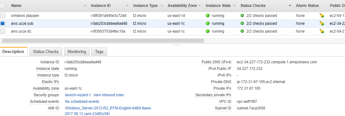
log into your EC2 and launch the 2012 R2 AMI , and accept all the defaults for now, you should end up with an EBS based instance
The root device type really is a statement about the storage of the root device , in the case of ebs this is a Amazon volume taken from an Amazon snapshot .
Below is the other type of storage the “instance” backed store , see its ephemeral that means that after you have turned the instance off , your data disappears
EBS backed storage uses physical volumes which means that your data will persists, even if you cycle your instance , which suits us on UCCE
The virtualization type hvm , refers to the type of virtualization used Amazon use either PV para virtualization or hvm which is hardware virtual machine the HVM comes with everything you need to run , where with PV you have to mess round with Grub to load your image
Increasing storage of ec2 instance work-around
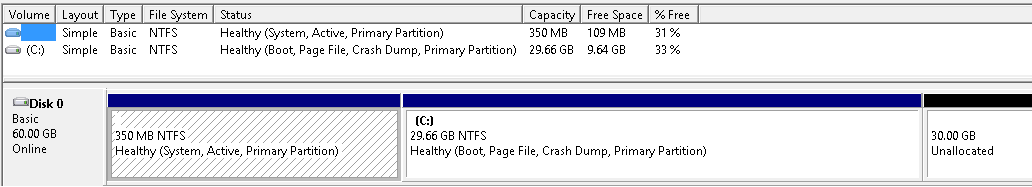
We have to change the size of the disk from 30GB to at least 60 GB , since 30 GB drive wont be able to support the Cisco ICM v11.0 software and the MS SQL 2014 environment. You cant do this at the provision storage page of the instance , when you first boot the AMI since it invalidates your free tier and it wont spin, but you can use the following work around to get yourself a bigger disk on the free tier via the elastic Block storage application .
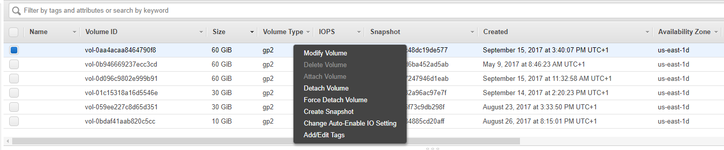
Elastic block storage modify volume
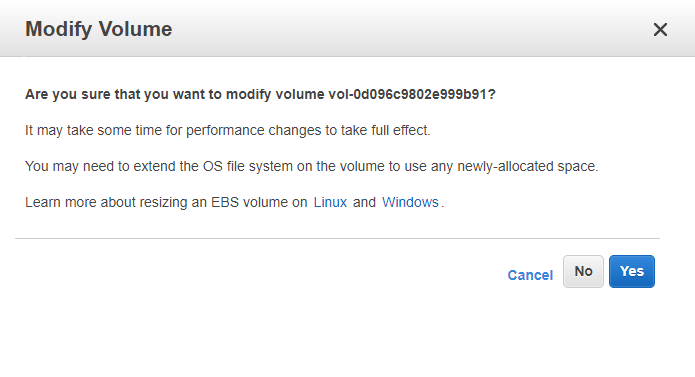
in the elastic block storage console select the volume for the instance you just created and select action , and then modify this will then spawn the box below
then change to 60 GB disk and select modify this should then spawn the following
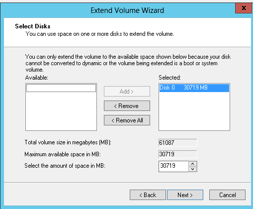
what a nice message from the Amazon engineers , so you will have to log into the instance after and then use disk tools to grab the extra space , if you monitor elastic block storage you will see the volume optimizing. We need to let this process complete before rebooting the instance and then reformatting the drive
Increasing volume on 2012 R2 Host (UCCE member server)
Log into your instance using the public IPV4 address of the instance you just created , you will use the root Administrator account for this (dont forget to put your rule into the security group for RDP access )
The head for the computer management snap in and select Disk management you should see the same GUI as shown below;
So you can see that we got the extra 30 GB via elastic block storage , even with the free tier restriction 😉 then right click on the C drive and select to extend the volume this should then spawn the confirmation below
Windows 2012 R2 DNS configuration for UCCE
so while we have an RDP session open to our EC2 UCCE server we may as well promote this into the AD domain we created earlier . Currently this server sits in an work group.To get the UCCE server to pick up its domain controller , the easiest way is to point the DNS of the server to the private IP address of the PDC. After this Pinging corp.ucce should resolve the private IP address of the PDC.
the change i made was here
Promoting UCCE server to corp.ucce Domain
Using the windows 2012 server manager on the UCCE member server select the work group hyperlink and then promote to the domain corp.ucce
If the DNS resolves this should pick up the private IP address of the domain controller , you should then ask to be authenticated use the account details you created in the AD 101 section and you should be able to add the domain after a reboot .
RDP to UCCE / EC2 @ corp.ucce
Use the credentials from AD 101 section when you need to log into the UCCE member server and of course use the public IPV4 address for the RDP session , or else your domain manager software (part of UCCE) will not find the corp.ucce domain.
Then the server manager should say your a member of corp.ucce
Exectute ICM software via S3
i used an S3 storage to store all the software i would need for the build , in this way i could browse the software i would need from the member server , and take advantage of the 1.4 mega bits per second that you tend to get within an availability zone. Also the other cool thing about windows 2012 is that it allows you to mount direct from the .ISO
so run the ICM base software first by running setup.exe in the folder highlighted. The setup should complete without incident and produce the GUI below
reboot the instance as suggested .
Running the UCCE Domain controller Applet
After the reboot connect to the EC2 instance via RDP. On the desktop now there should be a folder called , unified CCE tools , from this folder run the domain manager , this will use the PDC to bring down the OU structure of the domain to the nUCCE server
Staging the SQL server on nUCCE / ec2
Browse to the bucket where your SQL 2014 ISO is stored on S3 from nUCCE/EC2 instance and mount the ISO , then run the setup .exe and you should see GUI below
dont worry about the planning link for now but select the installation link and select the New SQL Server link, we are also going to use the evaluation version of SQL , which will give us 180 days worth, this can then be extended for another 180 , pretty much accept all defaults until;we get to the feature selection.
select the options shown , though for the build to complete we need to add the .NET framework 3.5 service pack 1 is required , this can be activated on the member server as a role, without doing this you will hit the issue below
Adding .NET role to nUCCE / ec2 via 2012 role manager
using the server manager app , underneath the manage key , then select the .net Microsoft framework
then after selecting next the install should progress as shown below
close the application after the the .NET feature has been installed. Then you should be able to re run the setup and pass the test. At the instance screen set below follow accept the default SQL instance
At the server configuration tab make the SQL services run under the NT AUTHORITY SYSTEM account and make all start up types automatic
then under the collation tab make the following changes and click apply
Then under the database engine configuration page choose mixed mode , a password for the SQL SA account and add current user and administrator user
then we are ready to install
then reboot the nUCCE instance in ec2 dashboard. I have breezed through the setup for SQL contact center a bit , but if you want a much more in depth view of the setup follow the link below
Now is a good time to take a snap shot of the nUCCE /ec2 server , since it has fresh AD, WIN 2012 , SQL 2014 and the basic ICM install software , but the final app has not been built yet and there is no contact center state , to create a snap shot follow the steps below
go to elastic block storage via the management console and select the volume ID for the nUCCE server right click and create snapshot , then under the snap shot you should see the back up created
SQL post install tweaks
This is the final stages of hosting the ICM part of a UCCE architecture on AWS , but we have to make the following tweaks in SQL config so we can get all the contact center components to build correctly .
using the SQL server configuration manager , for the client protocols move the named pipes above TCP/IP.Then under the SQL server network configuration enable Named Pipes.
Building the UCCE Components
On the desktop of the nUCCE server there should now be a unified ucce web set up short cut on the desktop which you can use to build the components it will take you to the web page below
login using the credentials of the account we set up in AD 101. This tools allows us to build the following ucce components
ICR intelligent call router
Logger
Admin workstation
These 3 component create the “brain” of the UCCE call center which allows you to make call routing decisions , in real time against a contact center state .
Adding the nUCCE instance
The first thing we need to add is an instance , which is basically the idea of a customer and assign an integer as shown below, the link to this is under the instance management tab in the left hand frame
Adding the nUCCE Logger
Add the logger under the logger tab except the defaults here
and except the defaults at the next tab
the host name of the server gets filled in by default and this resolves to the private address of the EC2 eg
Then at the next tab enable the outbound option , this later will be used to make outgoing SIP calls from nUCCE
Adding the nUCCE Router
We are going to basically follow the same process here to add the router , so on your desktop click the unified CCE web setup icon as before , use the credentials for your domain user and then from the left hand side click Router , accept the defaults shown below
Basically select side A and select Simplex and then click next;
As before the private of your EC2 instance resolves to the private IP address , this can be resolved via a ping.
This will match with what is on your EC2 instance desktop and Ec2 dashboard
and via your EC2 dashboard
at the next router install page enable 4 x PG ‘s as below
The PGs essentially provide us with a CTI interface to integrate third parties to.
Hopefully we can use lambda via connect to make a routing decision in cisco , hence the reason for enabling database routing option in the router. At the next screen accept the defaults for QoS , since essentially we are simplexed these will have no effect
Why did my private address for my EC2 instance change ?
That completes the build of the nUCCE Router. The more eagle eyed amongst you will see that the hostname changed between the router installation and the logger installation . This is only because i managed to kill my original install and had to re-stage , but the main point to take away is that in simplex , within a single availability zone for your EC2 instance , we are going to run all the services via a single private IP address , so your hostname will be the name provided by AWS when you launch the AMI
Building the nUCCE admin workstation.
Now that we have built the routing core within AWS , we need to build the administration interface so we can configure nUCCE / AWS . This basically follows the same steps as before , logging into the web interface on the desktop of your EC2 instance and then taking the following configuration options.
then select the options below
then finally as below
since there is no duplex in this architecture , we dont need a secondary site , but since it’s a required item we can just use a placeholder of secondary to satisfy the install .
The network interfaces for the AW is defined as below
again we are going to use the hostname of our EC2 instance which resolves to the private address EC2 instance.
Summary
That basically concludes the build , what we have done is implement the core intelligence of the Cisco UCCE v 11.01 product over AWS.
if you click the unified CCE service control applet on the EC2 desktop you should see the services built as below
dont worry about the PG / CG and dialer nodes (you will have the router , logger and distributor nodes) , i will blog the build of these components in a later blog , where we will use them to pass calls between connect and UCCE.
If you have any questions , or need help or assistance in building your own UCCE v 11.0 sandbox over AWS please dont hesitate to reach out to me on [email protected].